Air cleaner for engine of vehicle

Active Publication Date: 2005-11-03
KAWASAKI MOTORS LTD
View PDF15 Cites 15 Cited by
  • Summary
  • Abstract
  • Description
  • Claims
  • Application Information

AI Technical Summary

Benefits of technology

[0022] In the air cleaner of the present invention, since the top cover and the element supporting member ar

Problems solved by technology

Therefore, the manufacturing cost thereof increases due the increase

Method used


Image

  • Air cleaner for engine of vehicle
  • Air cleaner for engine of vehicle
  • Air cleaner for engine of vehicle

Examples


Embodiment Construction

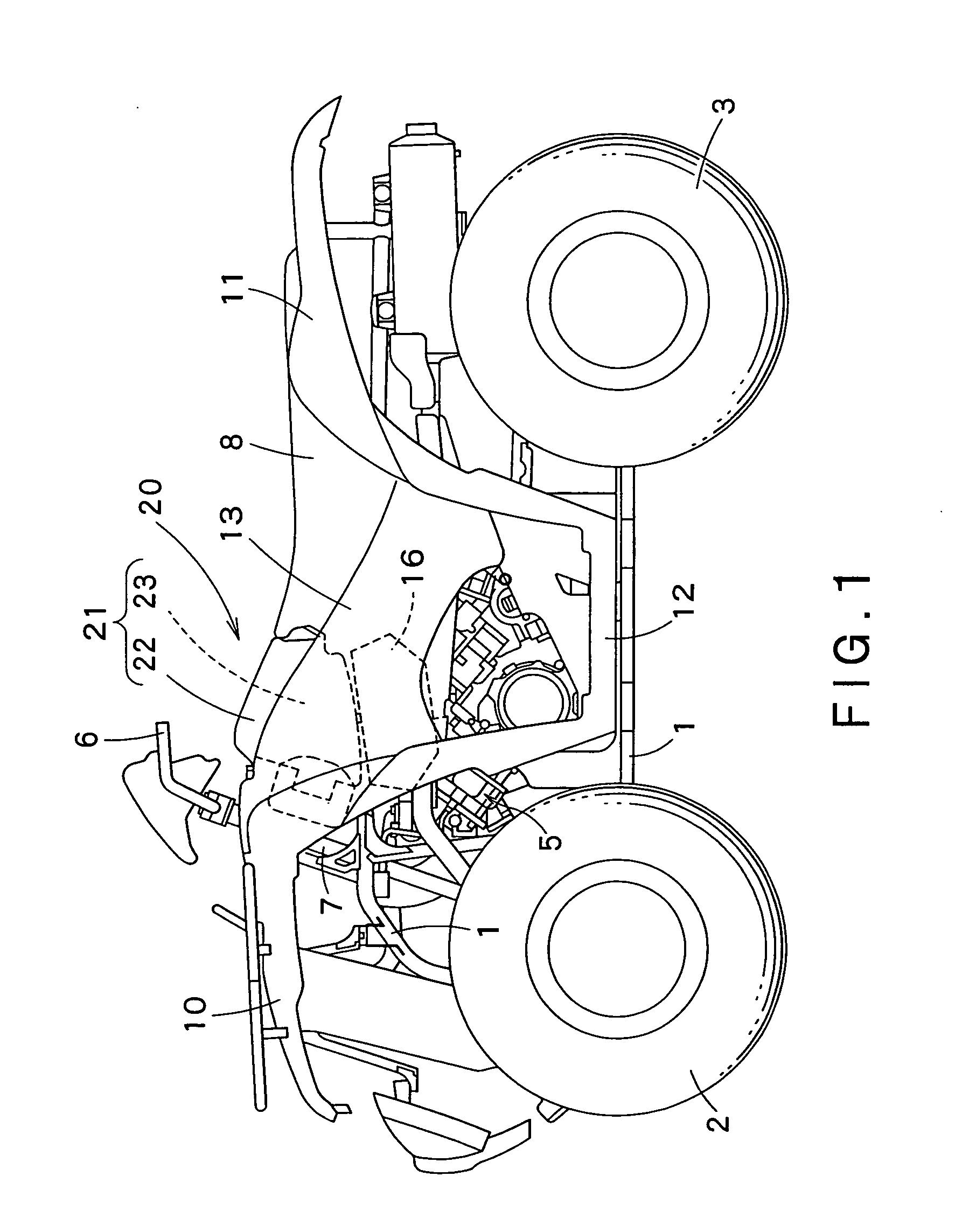
[0035] General Construction of Vehicle

[0036] Referring to FIG. 1 showing an all-terrain straddle-type four-wheel vehicle provided with an air cleaner 20 in a preferred embodiment according to the present invention, right and left front wheels 2 and right and left rear wheels 3 are suspended from a front part and a rear part, respectively, of a body frame 1, and an engine 5 is supported on the body frame 1 in a space between the front wheels 2 and the rear wheels 3. A steering shaft 7 is disposed in front of the engine 5. A steering handlebar 6 is attached to the upper end of the steering shaft 7. A seat 8 is disposed at an elevated position behind the engine 5. Front fenders 10 and rear fenders 11 are extended over the front wheels 2 and the rear wheels 3, respectively. Foot boards 12 are disposed on the right and the left side, respectively, of the lower end of the engine 5. The right and the left side of an upper part of the engine 5 are covered with side covers 13, respectively....


PUM

PropertyMeasurementUnit
Shapeaaaaaaaaaa

Abstract

The present air cleaner for an engine of a vehicle, includes: a cleaner case; and a filter assembly disposed in the cleaner case. The filter assembly includes a cylindrical cleaner element, an element supporting member supporting a lower end of the cleaner element and an inner circumferential surface of the cleaner element so that the cleaner element is kept in a predetermined cylindrical shape, and a plate-shaped top cover detachably fastened on an upper surface of the element supporting member so as to press an upper end of the cleaner element downward.

Description

CROSS REFERENCE TO RELATED APPLICATIONS [0001] This application is based upon and claims the benefit of priority from the prior Japanese Patent Application No. 2004-133855, filed on Apr. 28, 2004, the entire contents of which are incorporated herein by reference. BACKGROUND OF THE INVENTION [0002] 1. Field of the Invention [0003] The present invention relates to an air cleaner for an engine mainly mounted on a straddle-type vehicle such as a straddle-type four-wheel vehicle or a motorcycle. [0004] 2. Description of the Related Art [0005]FIG. 10 shows a known air cleaner 100 mounted on a vehicle such as a straddle-type four-wheel vehicle (JP-A 2003-286916). The air cleaner 100 has a cleaner case 101 formed by joining together an upper case member 102 and a lower case member 103. The cleaner case 101 contains a filter assembly 105 therein. A cleaner inlet (air intake port) 110 is formed on the side wall of the lower case member 103. A cleaner outlet (air outlet port) 111 to be connect...

Claims


Application Information

Patent Timeline
IPC IPC(8): B62J99/00F02M35/02F02M35/024F02M35/10F02M35/16
CPCF02M35/162F02M35/0203
Inventor TAKANO, KIYOHITOKOBAYASHI, YASUTAKAKUYAMA, KOHEI
Owner KAWASAKI MOTORS LTD
Why Eureka
Try Eureka