Apparatus and method for drilling and reaming a borehole

a technology for reaming apparatus and boreholes, which is applied in the direction of drilling pipes, directional drilling, cutting machines, etc., can solve the problems of increasing the time and cost required to drill the borehole, and reducing the accuracy of drilling. the effect of reaming the diameter of the reamer

Inactive Publication Date: 2005-11-03
HALLIBURTON ENERGY SERVICES INC
View PDF7 Cites 48 Cited by
  • Summary
  • Abstract
  • Description
  • Claims
  • Application Information

AI Technical Summary

Benefits of technology

[0018] Certain embodiments described herein include a fixed blade and at least one extendable member that can be extended to adjust and enlarge the diameter of the reamer. Once the assembly has been passed beneath the existing borehole, with its extendable members in the contracted position, the members can then be extended and the assembly rotated to form a larger diameter borehole. The extendable members may be elongate blades or other structures, such as pads or pistons. It is desirable that a plurality of cutter elements be mounted on one or more of the blades of the reamer so as to ream the borehole formed by the pilot bit to the desired larger diameter, and also to provide a means for back reaming the hole as the drilling assembly is raised or removed from the borehole. The cutter elements may be placed on the fixed blade, the extendable blades, or both. In certain preferred embodiments, the fixed blade is releasably affixed to the reamer housing so that blades having greater or lesser radial extension may be substituted for a given blade. The back reaming capabilities of these embodiments offer substantial savings in time and cost as compared with traditional assemblies that cannot back ream and that, where back reaming is desired, would require an additional trip of the drill string.
[0019] Certain embodiments of the invention also include means for retaining the extendable members in their contracted position until it is desirable to expand the diameter of the tool for reaming, such as after the drilling assembly has passed through the smaller, preexisting borehole. The latching retainers may include shear pins that prevent the extendable members from moving until the pressure of the drilling fluid being pumped through the reamer reaches a predetermined fluid pressure. In certain preferred shear pins, the pins include a head portion, a shank portion, and a reduced diameter portion along the shank such that, upon the predetermined fluid pressure being exceeded, the pin will shear at the reduced diameter portion allowing the moveable member to extend. The shear pin preferably is disposed in a bore formed in the outer surface of the reamer housing so that it is accessible without requiring disassembly of the reamer. This arrangement facilitates quick and simple field replacement or substitution the shear pin. The latching retainers may likewise be non-shearing members, such as spring biased latching members having an extension that is biased to engage a recess in the movable member and that disengages upon a predetermined drilling fluid pressure. A latching retainer is also disclosed for releasably and repeatedly locking the movable member in its extended position.
[0020] Providing cutter elements on all the blades of the reamer permits the reamer blades to be designed so that the cutting forces may be closer to being balanced, thereby reducing lateral loads on the movable members such as pistons and blades. Further, the drilling assembly and reamer described herein allow the formation of a larger diameter borehole beneath a casing string without requiring the use of a bi-center bit which, because it is not mass balanced, may cause bit wobble and deviation from the desired drilling path. This mass imbalance of a bi-center bit may also assist in causing the pilot bit to drill an oversized hole which will cause the reamer section to drill an undersized hole.
[0022] Other embodiments of the invention include a damping means to restrict the velocity at which the moveable members may move from the extended position toward the contracted position. This feature is desired because as the reamer is rotated in the borehole, formation projections and the resulting forces from the formation will tend to bias the extending member toward its contracted position. One dampening means for slowing the inward movement of the extendable member includes an orifice that restricts the volume of fluid flow as the extendable member is pushed toward the contracted position.

Problems solved by technology

This, of course, requires an extra trip of the drill string and thus is costly and undesirable in most cases.
In supporting the additional casing strings within the previously run strings, the annular space around the newly installed casing string is limited.
When this occurs, the broken components must be “fished” from the hole before drilling can continue, thus greatly increasing the time and cost required to drill the borehole.
However, since the reamer section is eccentric, the reamer section tends to cause the bit axis angle to slightly shift during its rotation, thus pointing the bit in different directions, and therefore to deviate from the desired trajectory of drilling the well path.
In certain formations, these lateral forces can cause the pilot bit to drill its portion of hole oversize, and thus the reamer section of the bi-center bit to drill an undersized hole.
However, space limitations in the casing, through which all components of the drilling assembly must pass has, in the past, prevented the placement of a “near-bit” stabilizer adjacent to a bi-center bit.
Conventional bi-center bits, however, cannot effectively be used to “back ream” the newly formed borehole because of a lack of adequate stabilization.
More specifically, as the drilling assembly having the bi-center bit is withdrawn, the pilot bit does not provide the stabilization needed to cause the winged blade to ream properly.
Thus, the reamer of the bi-center bit is not sufficiently stabilized by the pilot bit to permit effective back reaming.
Such higher pressures or fluctuations in pressures may cause sloughing off of formation material into the borehole.
However, that practice required an extra trip of the drill string and thus was time consuming, costly and undesirable.
However, without a near bit stabilizer, the specialized bit for drilling the casing shoe could not provide back reaming as the bit is removed from the borehole due to the formation pushing the drilling assembly off center, as previously discussed.
However, when drilling through the cement or other material of the casing shoe, high fluid pressure may be required as compared to that used merely to pass the drilling assembly to the bottom of the existing casing.
This increase in fluid pressure could cause the extendable stabilizer blades of a stabilizer such as that disclosed in U.S. Pat. No. 6,213,226 to extend prematurely, detrimentally effecting the ability of the bit to drill out the casing shoe.
Alternatively, premature blade extension while the shoe is being drilled may damage the stabilizer blades, rendering them ineffective or less effective in guiding the bit along the intended drilling path after the casing shoe has been drilled out.

Method used


Image

  • Apparatus and method for drilling and reaming a borehole
  • Apparatus and method for drilling and reaming a borehole
  • Apparatus and method for drilling and reaming a borehole

Examples


Embodiment Construction

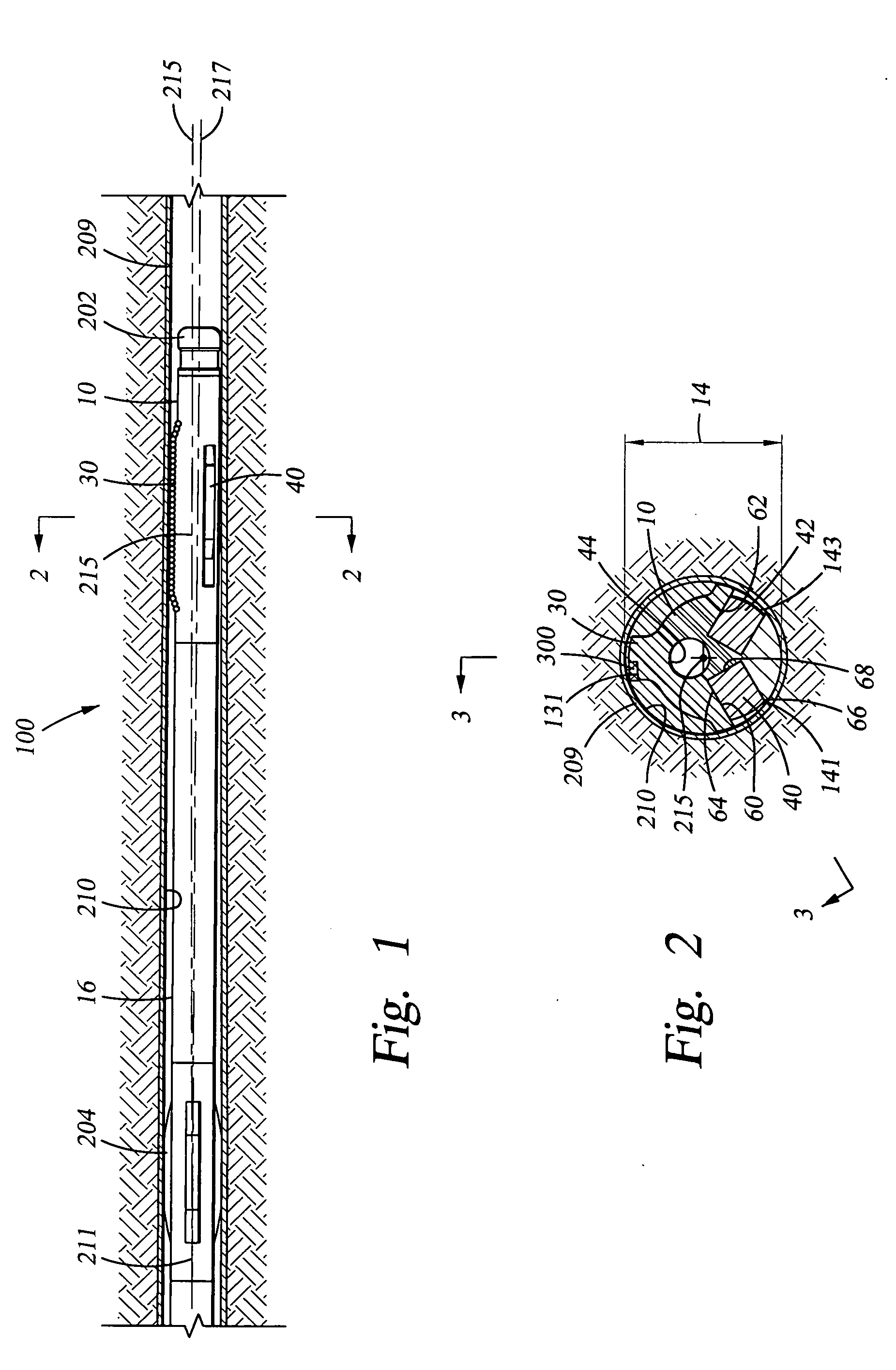
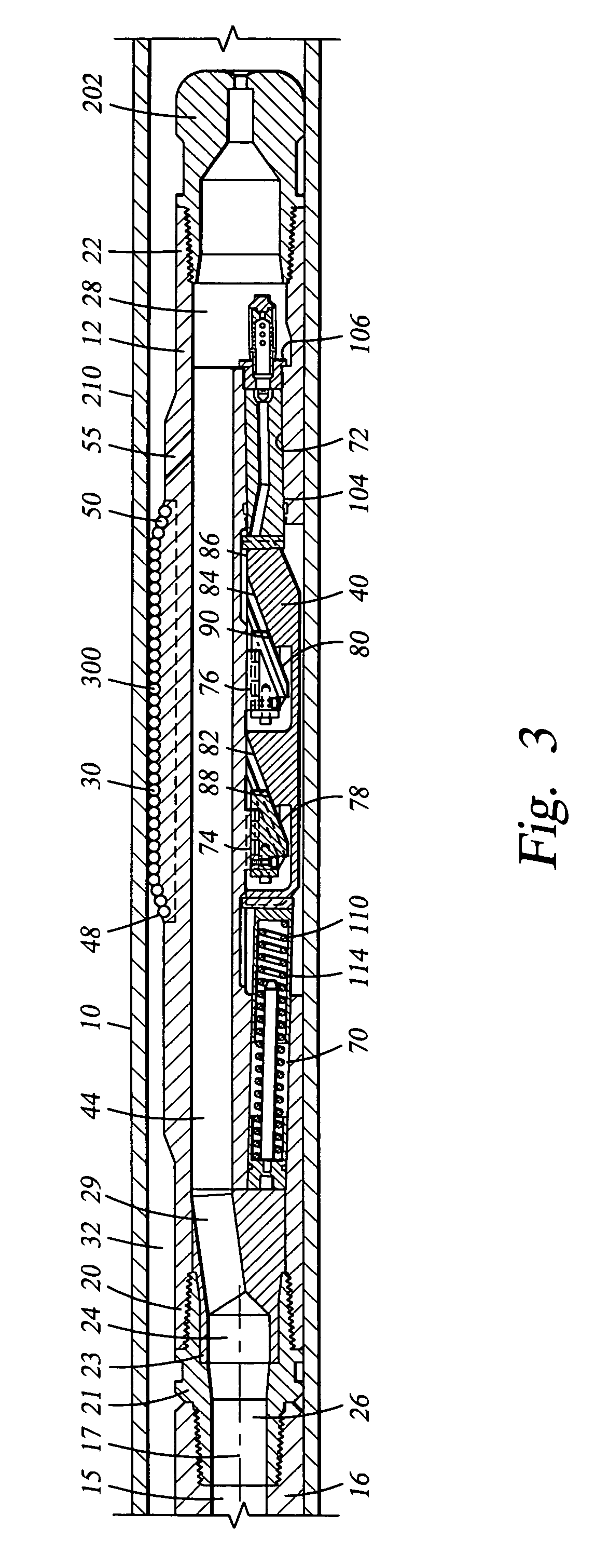
[0017] The embodiments described herein provide a drilling assembly useful in various applications. A first embodiment includes a pilot bit and an eccentric, adjustable diameter reamer above the pilot bit. The assembly may be passed through an existing borehole (cased or opened) and employed to drill at a diameter that is larger than the diameter of the hole above.

[0018] Certain embodiments described herein include a fixed blade and at least one extendable member that can be extended to adjust and enlarge the diameter of the reamer. Once the assembly has been passed beneath the existing borehole, with its extendable members in the contracted position, the members can then be extended and the assembly rotated to form a larger diameter borehole. The extendable members may be elongate blades or other structures, such as pads or pistons. It is desirable that a plurality of cutter elements be mounted on one or more of the blades of the reamer so as to ream the borehole formed by the pil...


PUM


Abstract

A drilling assembly and an eccentric, adjustable diameter reamer are disclosed. The reamer includes cutter elements mounted on at least a first fixed blade for reaming a previously-formed borehole or for forming a borehole of increased diameter beneath an existing cased borehole. The method and apparatus provide for stabilizing the drilling assembly so that the reamer may be used in back reaming the hole. Retainer means, such as shear pins or spring-biased reciprocating latch members, are provided to prevent premature extension of the reamer's moveable members, including blades and pistons. The shear pins are preferably accessible from the outer surface of the reamer housing so as to expedite field replacement of the shear pins without requiring disassembly of the reamer. The spring-biased latching members repeatedly latch and unlatch so that field replacement is not required, and so that the movable members may be extended and contracted multiple times while the reamer is downhole.

Description

CROSS-REFERENCE TO RELATED APPLICATIONS [0001] This is a divisional application of pending U.S. patent application Ser. No. 10 / 304,842, filed Nov. 26, 2002, which is a continuation-in-part application of U.S. Pat. No. 6,494,272, filed Nov. 22, 2000, which is a divisional of U.S. Pat. No. 6,227,312, filed Oct. 27, 1999, which is a divisional of U.S. Pat. No. 6,213,226, filed Dec. 4, 1997, each incorporated herein by reference. U.S. patent application Ser. No. 10 / 304,842, filed Nov. 26, 2002, is also a continuation-in-part application of U.S. Pat. No. 6,448,104, filed Jun. 27, 2000, which is a continuation of U.S. Pat. No. 6,213,226, filed Dec. 4, 1997, each incorporated herein by reference.STATEMENT REGARDING FEDERALLY SPONSORED RESEARCH OR DEVELOPMENT [0002] Not Applicable. BACKGROUND OF THE INVENTION [0003] The present invention relates to systems and apparatus for drilling boreholes in the earth for the ultimate recovery of useful natural resources, such as oil and gas. More parti...

Claims


Application Information

Patent Timeline
Patent Type & Authority Applications(United States)
IPC IPC(8): E21B7/08E21B10/32E21B17/10
CPCE21B10/325E21B10/322E21B7/06E21B7/28
Inventor EPPINK, JAY M.ODELL, ALBERT C. II
Owner HALLIBURTON ENERGY SERVICES INC
Why Eureka
Try Eureka