
Bedrock drilling and excavating apparatus

Inactive Publication Date: 2005-11-03
CHUAN HOME MACHINERY
View PDF1 Cites 8 Cited by
  • Summary
  • Abstract
  • Description
  • Claims
  • Application Information

AI Technical Summary

Benefits of technology

[0006] Therefore the primary object of the invention is to provide a drilling and excavating apparatus that receives power from a rotational power source. A pneumatic unit is provided which may vibrate up and down reciprocally to drive a drill to strike continuously downward under the gravity of the drilling and excavating apparatus to shatter the bedrock. A drill shell is provided that may be altered according to the diameter of the service shaft without changing the diameter of the pneumatic unit. The drill shell has a plurality of conical drill gimlets located thereon and arranged in different biased angles to strike and shatter bedrock effectively, and the drilling and excavation speed may increase.
[0008] Another object of the invention is to provide an excavator to remove shattered rocks and waste soils from the service shaft while the drilling operation is proceeding in a single process, thereby to increase drilling and excavating efficiency.
[0009] Yet another object of the invention is to reduce the cost and prevent dusts from drifting and spreading.

Problems solved by technology

When drilling deeper into the stratum, the stratum becomes harder and drilling speed is slower.
Sometimes drilling and excavation operations cannot be continued and have to stop.
The drill structure of having the high hardness steel ball on one end is expensive.
Moreover, to strike the hard bedrock through the high hardness steel ball is easy to damage the drill.
It is less likely to create large cracks on the bedrock, and the drill is easily damaged.
The rotating drill that sinks deeply into the stratum often generates a great amount of dusts which spread like water fall.
This results in an undesirable working environment and is harmful to the workers.
It will result in higher costs, increased operation time and greater risks.
The heavy machinery used on the construction site usually is bulky and heavy.
Operation is tedious and risk on the construction site is higher.

Method used


Image

  • Bedrock drilling and excavating apparatus
  • Bedrock drilling and excavating apparatus
  • Bedrock drilling and excavating apparatus

Examples


Embodiment Construction

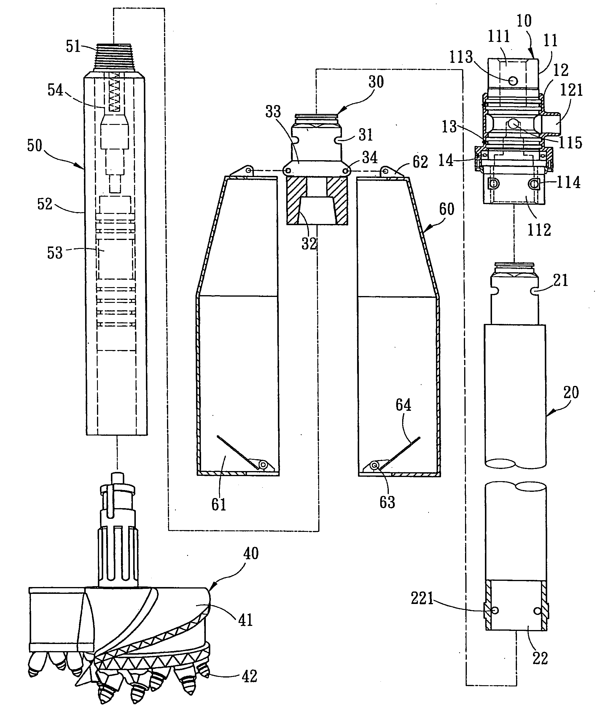
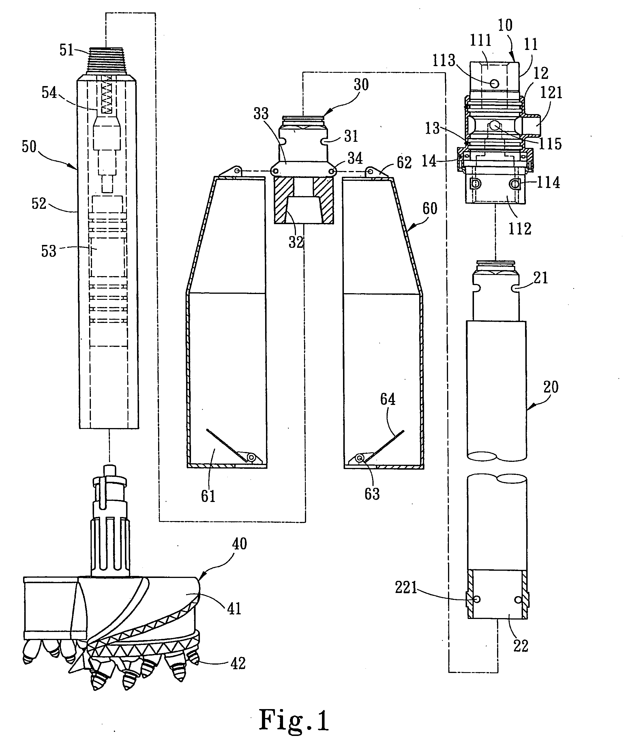
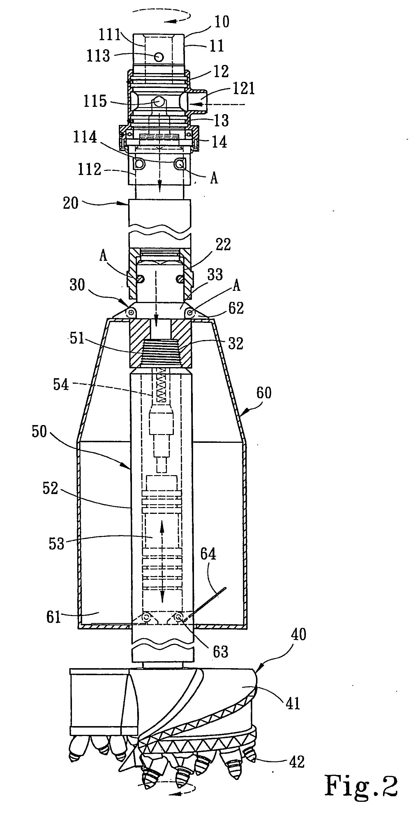
[0019] Please referring to FIGS. 1 and 2, the apparatus according to the invention includes:

[0020] a coupling device 10 to connect and transmit a rotational power source and channel air intake of an air pressure source to generate vibration. It includes a coupling axle 11 and an air intake hood 12 coupling on the periphery of the coupling axle 11. The coupling axle 11 has a first housing trough 111 on an upper end to couple with a driving shaft (not shown in the drawings) and a fastening bore 113 to receive a pin A to fasten the driving shaft to the upper end of the coupling axle 11. The coupling axle 11 has a second housing trough 112 on a lower end and fastening bores 114 on two sides. The second housing trough 112 has an aperture115 in the middle formed in a normal and cross manner. The air intake hood 12 is located around the aperture 115 and has an air inlet 121 on one side connecting to the air pressure source to receive compressed air into the coupling axle 11 through the ap...


PUM


Abstract

A bedrock drilling and excavating apparatus receives power from a rotational power source to drive a drill to strike and shatter bedrock under the gravity of the apparatus and reciprocal vibrations of a pneumatic unit located on the apparatus. The apparatus includes a coupling device to couple with the rotational power source and an air intake vibration structure, a coupling sleeve which has one end coupling with the lower end of a coupling axle and a connector which further couples to the pneumatic unit, and a drill coupling to the pneumatic unit. The pneumatic unit drives the drill to vibrate up and down reciprocally to strike and shatter bedrock. The drill has a drill shell which is alterable according to the diameter of the service shaft without changing the diameter of the pneumatic unit. The drill shell has a plurality of conical drill gimlets mounted thereon in different biased angles to shatter the bedrock and improve drilling and excavating effect.

Description

FIELD OF THE INVENTION [0001] The present invention relates to a bedrock drilling and excavating apparatus and particularly to a drilling and excavating apparatus that receives power from a rotational power source and has a pneumatic unit vibrating up and down reciprocally to drive drill gimlets to strike continuously downwards under the gravity of the drilling and excavating apparatus to shatter the bedrock. BACKGROUND OF THE INVENTION [0002] Drilling and excavating apparatus are generally being used on construction sites to drill and excavate the stratum. The stratum generally can be divided into soft stratum and hard stratum depending on the areas. In the countries of Southeast Asia (Such as Malaysia) the stratum usually is a hard type bedrock. The hardness increases as the depth of the bedrock increases. [0003] The drills used in the conventional drilling and excavating operation such as the one disclosed in R.O.C. patent publication No. 356896 entitled “Improved structure for d...

Claims


Application Information

Patent Timeline
IPC IPC(8): E21B4/10E21B6/04E21B7/00E21B47/026
CPCE21B4/10E21B7/006E21B7/005E21B6/04
Inventor LEE, CHIN-YI
Owner CHUAN HOME MACHINERY
Learn More