Injector having structure for controlling nozzle needle

a technology of injector and nozzle needle, which is applied in the direction of fuel injecting pump, machine/engine, mechanical equipment, etc., can solve the problems of inability to achieve the downsizing of the solenoid, excessive slowed back pressure chamber and excessive speed of the nozzle needle back pressure chamber

Inactive Publication Date: 2005-11-03
DENSO CORP
View PDF7 Cites 20 Cited by
  • Summary
  • Abstract
  • Description
  • Claims
  • Application Information

AI Technical Summary

Problems solved by technology

However, due to the choking effect or throttling effect induced by reducing of the diameter of the seat, a pressure decreasing speed of the nozzle needle back pressure chamber may be excessively slowed to affect the responsibility of the nozzle needle.
Thus, in the case of increasing the lift amount of the control valve, a relatively large attractive force is required, and therefore the downsizing of the solenoid cannot be achieved.

Method used


Image

  • Injector having structure for controlling nozzle needle
  • Injector having structure for controlling nozzle needle
  • Injector having structure for controlling nozzle needle

Examples


first embodiment

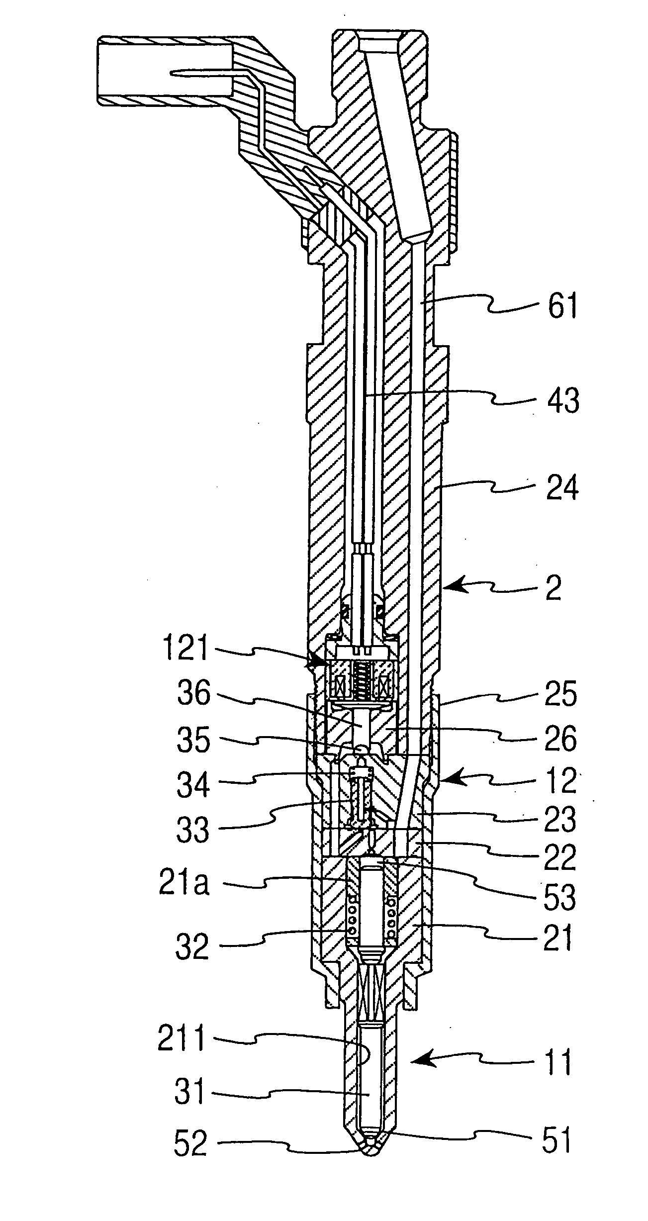
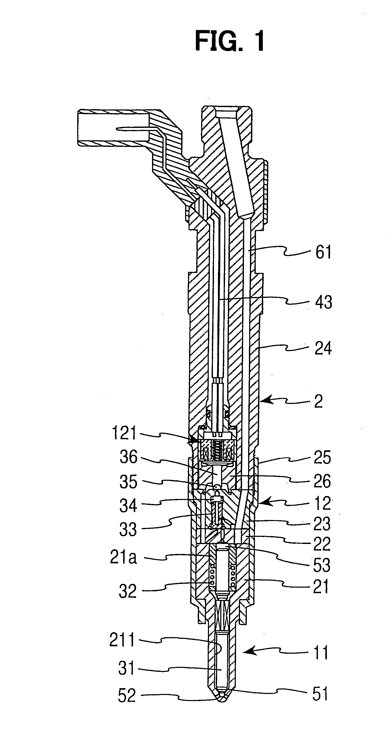
[0041]FIGS. 1 and 2 show a structure of an injector according to a first embodiment of the present invention. The injector is used in an internal combustion engine, such as, a diesel engine having a common rail type fuel injection system and is provided to each cylinder of the engine. The injector is controlled by an ECU to inject fuel, which is supplied from a common rail, for a predetermined time period.

[0042] The injector includes an elongated base body 2 of a generally cylindrical configuration. The base body 2 includes a nozzle body 21, a distance piece 22, a first valve body 23, a holder 24 and a retaining nut 25. The nozzle body 21, the distance piece 22, the valve body 23 and the holder 24 are axially arranged in this order from a downstream end side of the injector and are held together by the retaining nut 25.

[0043] Various recesses and holes are formed in the base body 2 to receive corresponding components and to form fuel passages. A nozzle arrangement 11, which projec...

second embodiment

[0062]FIG. 8 shows an injector according to a second embodiment of the present invention. In this embodiment, a portion of the structure of the injector of the first embodiment is changed, and the components similar to those of the first embodiment will be indicated by the same numerals. In the following description, the portion of the structure of the injector, which is different from that of the first embodiment, will be mainly described.

[0063] The base body 2A of the second embodiment is basically the same as that of the first embodiment. However, a distance piece 22a and a closing member 27A of the second embodiment are different from the distance piece 22 and the closing member 27 of the first embodiment. A high pressure branch passage 67, which branches from the high pressure passage 61 and is communicated to the needle back pressure chamber 53, is formed in the distance piece 22A to always communicate between the needle back pressure chamber 53 and the high pressure passage ...

third embodiment

[0066]FIG. 9 is a diagram indicating the lift amount of the nozzle needle 31 and the pressure of the nozzle chamber 51 in the injector of the first embodiment with respect to the fuel injection time period. After the starting of the fuel injection, the pressure of the nozzle chamber 51 is reduced (the pressure drop). It is effective to provide an accumulator chamber in the high pressure passage to limit such a drop in the pressure. For example, as shown in FIG. 10, in the injector of the first embodiment, the inner diameter of a longitudinal hole 242, which is provided to form the high pressure passage 61, may be enlarged for a predetermined depth from the opposed end surface, which is opposed to the first valve body 23 of the holder 24. With this structure, the wall of the holder 24 is substantially thinned at the outer peripheral part of the longitudinal hole 241 to provide the space for the second valve needle 36 and the solenoid 121. Furthermore, as one possible example, the hol...


PUM


Abstract

A valve back pressure chamber is provided to exert a back pressure of a first valve needle. Furthermore, a hydraulic pressure passage is provided to extend through the valve back pressure chamber. A valve body is provided to a second valve needle and is driven to connect and disconnect between the hydraulic pressure passage and a fuel tank and thereby to drive the first valve needle. The second valve needle is driven by hydraulic pressure induced by an actuator.

Description

CROSS REFERENCE TO RELATED APPLICATION [0001] This application is based on and incorporates herein by reference Japanese Patent Application No. 2004-135371 filed on Apr. 30, 2004, Japanese Patent Application No. 2005-20904 filed on Jan. 28, 2005, Japanese Patent Application No. 2005-40730 filed on Feb. 17, 2005 and Japanese Patent Application No. 2005-67272 filed on Mar. 10, 2005. BACKGROUND OF THE INVENTION [0002] 1. Field of the Invention [0003] The present invention relates to an injector and more particularly to a structure for controlling a nozzle needle of the injector, which is driven to enable and disable inject fuel. [0004] 2. Description of Related Art [0005] In an injector used in a common rail type fuel injection system of a diesel engine, a nozzle needle, which is driven to enable and disable fuel injection, is controlled by an actuator, such as a solenoid, to freely set fuel injection timing and an amount of fuel injection and thereby to achieve advanced fuel injection...

Claims


Application Information

Patent Timeline
Patent Type & Authority Applications(United States)
IPC IPC(8): F02M47/00F02M47/02F02M51/06F02M55/00F02M59/00F02M61/10F02M61/16F02M63/00
CPCF02M47/027F02M55/007F02M61/168F02M63/0029F02M63/004F02M2547/006F02M63/0045F02M63/0054F02M2200/40F02M2200/8084F02M63/0043
Inventor FUNAI, KENJIKUROYANAGI, MASATOSHISHIBATA, AKIRADATE, KENJI
Owner DENSO CORP
Why Eureka
Try Eureka