Plasma display panel

a technology of display panel and plasma, which is applied in the direction of gas discharge vessel/container, electrode, gas-filled discharge tube, etc., can solve the problems of adversely affecting discharge characteristics, affecting the efficiency of pdp improvement, and causing mis-discharge between adjacent discharge cells in this direction, so as to improve the exhaust efficiency, improve the discharge efficiency, and prevent bright image sticking

Inactive Publication Date: 2005-11-03
SAMSUNG SDI CO LTD
View PDF4 Cites 14 Cited by
  • Summary
  • Abstract
  • Description
  • Claims
  • Application Information

AI Technical Summary

Benefits of technology

[0021] In view of the foregoing, the structures of the barrier ribs are optimized to increase discharge efficiency. Also, the temperature over the entire plasma display panel is made more uniform by the presence of the non-discharge regions to thereby prevent bright image sticking, which results from the concentration of heat in specific areas. The non-discharge regions also act as paths through which contents in the plasma display panel may be exhausted to thereby improve exhaust efficiency. Finally, a deformation of the barrier ribs during firing of the barrier ribs is prevented to thereby reduce noise generated by the plasma display panel.

Problems solved by technology

However, a problem with forming the display electrodes 114 in the stripe pattern and the barrier ribs 105 in the stripe pattern as described above is that crosstalk may occur between adjacent discharge cells, that is, between the discharge cells adjacent along direction Y. Further, since the discharge cells are communicating between each adjacent pair of the barrier ribs 105 (i.e., along direction X), there is the possibility of mis-discharge occurring between the adjacent discharge cells in this direction.
However, this runs counter to efforts for improving PDP efficiency.
However, mis-discharge problems along the direction that the barrier ribs are formed still remain with this structure.
However, in the matrix type of barrier rib structure, since all areas except those directly corresponding to where the barrier ribs are formed are areas where discharge takes place, there are no regions in the PDP that absorb or disperse heat, only areas that generate heat.
Such temperature differences not only adversely affect discharge characteristics, but are also the cause of other problems such as brightness differences and bright image sticking.
Another prior art drawback relates to the manufacture of the PDP.
However, a problem with forming barrier ribs using these methods is that during the firing process, organic material contained in the barrier rib material is removed such that the barrier ribs shrink and are otherwise deformed.
Such deformation of the barrier ribs is particularly severe at end areas of the barrier ribs in non-display regions of the PDP.
One negative consequence of such deformation of the barrier ribs is that the noise generated by the PDP may become severe.

Method used


Image

  • Plasma display panel
  • Plasma display panel
  • Plasma display panel

Examples


Embodiment Construction

[0030] Exemplary embodiments of the present invention will now be described with reference to the drawings.

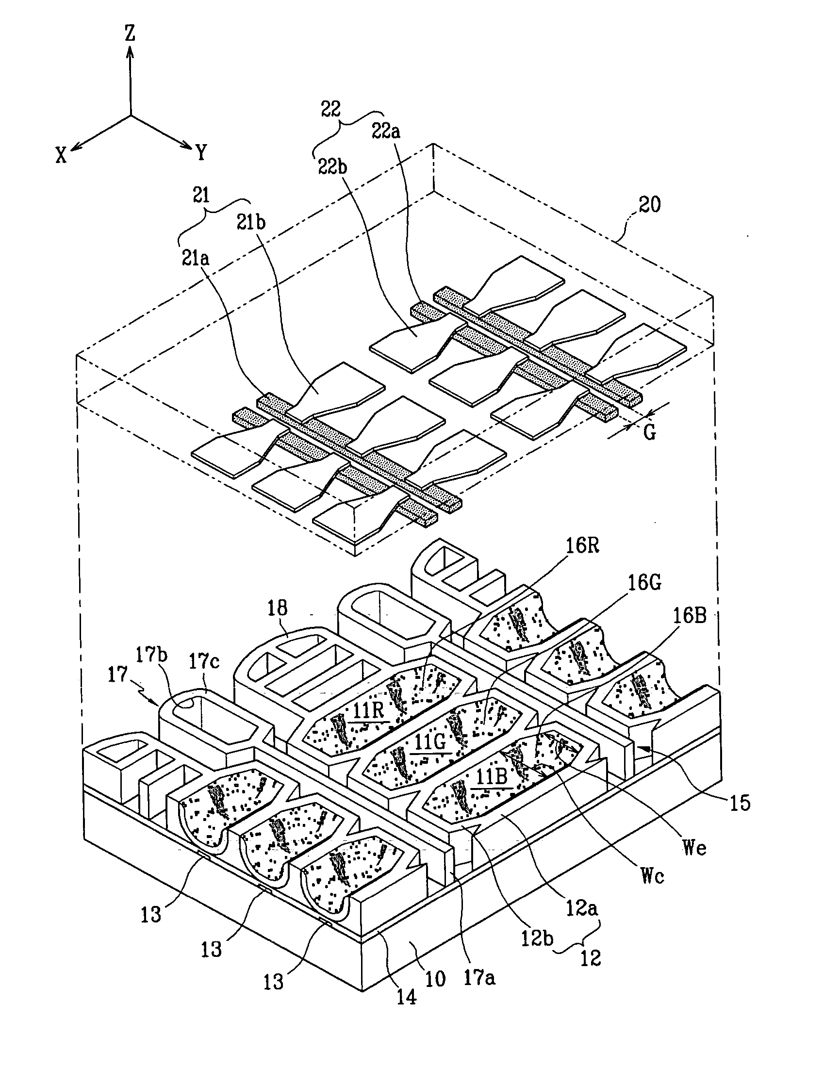
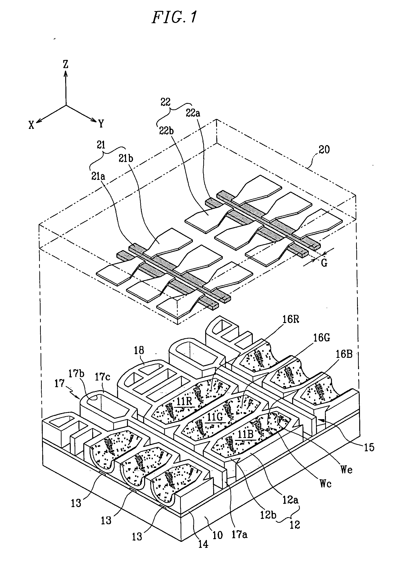
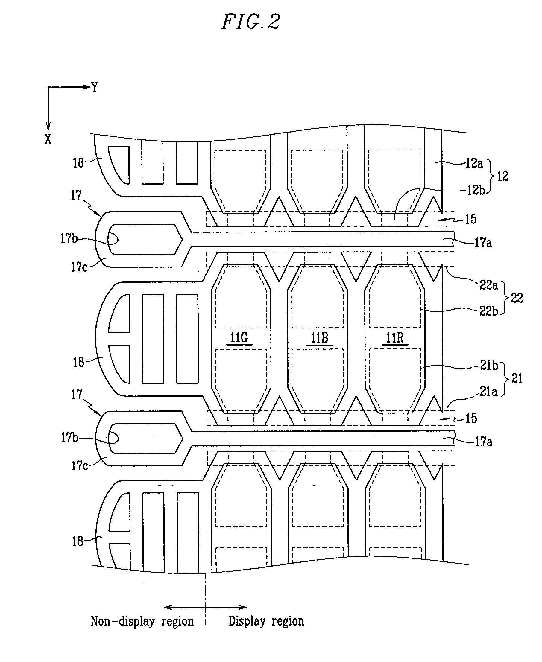
[0031]FIG. 1 is a partial exploded perspective view of a plasma display panel (PDP) according to a first exemplary embodiment of the present invention, and FIG. 2 is a partial plan view of the PDP.

[0032] With reference to the drawings, the PDP according to the first exemplary embodiment of the present invention includes a first substrate 10 and a second substrate 20 provided opposing one another with a predetermined gap therebetween. Formed on a surface of the first substrate 10 opposing the second substrate 20 are a plurality of address electrodes 13. The address electrodes 13 are formed in a stripe pattern along a first direction, which is perpendicular to a second direction. The first direction along which the address electrodes 13 extend substantially corresponds to direction X in FIG. 1. In the description to follow, directions X and Y (first and second directions) will ...


PUM


Abstract

A plasma display panel includes a first substrate, and a second substrate opposing the first substrate. A plurality of address electrodes are formed on the first substrate along a first direction, and a plurality of barrier ribs are mounted between the first and second substrates and defining a plurality of discharge cells that are formed into a plurality of rows along a second direction which is substantially perpendicular to the first direction. Non-discharge regions are formed between the respective rows of the discharge cells, and a plurality of transverse barrier ribs are formed along the second direction respectively within the non-discharge regions. Each of a plurality of phosphor layers is formed in a respective one of the discharge cells. Display electrodes are formed on the second substrate. At least one end of each of the transverse barrier ribs includes an annular branched segment.

Description

CROSS-REFERENCE TO RELATED APPLICATION [0001] The present application claims priority to and the benefit of Korean Patent Application No. 10-2004-0029915 filed on Apr. 29, 2004 in the Korean Intellectual Property Office, the entire content of which is incorporated herein by reference. BACKGROUND OF THE INVENTION [0002] 1. Field of the Invention [0003] The present invention relates to a plasma display panel (PDP), and more particularly, to a PDP having a structure in which each discharge cell is independently defined by barrier ribs formed between two substrates. [0004] 2. Description of the Related Art [0005] A PDP is a display device that displays images through the excitation of phosphors. Vacuum ultraviolet (VUV) rays emitted through plasma discharge are used to excite the phosphors. The PDP is experiencing ever-increasing widespread use because of its thin profile and ability to be made with large screen sizes. [0006]FIG. 7 shows a partial exploded perspective view of a conventi...

Claims


Application Information

Patent Timeline
Patent Type & Authority Applications(United States)
IPC IPC(8): H01J11/12H01J11/22H01J11/24H01J11/26H01J11/34H01J11/36
CPCH01J11/12H01J11/24H01J2211/54H01J2211/245H01J2211/368H01J11/36
Inventor SONG, SUNG-HOKWON, JAE-IKKIM, WOO-TAE
Owner SAMSUNG SDI CO LTD
Why Eureka
Try Eureka