Film-mode (3:2/2:2 Pulldown) detector, method and video device

a detector and film-mode technology, applied in the field of video devices, can solve the problems of slow movement, inability to reliably check flags, and often poorly edited videos,

Inactive Publication Date: 2005-11-03
AVAGO TECH INT SALES PTE LTD
View PDF7 Cites 45 Cited by
  • Summary
  • Abstract
  • Description
  • Claims
  • Application Information

AI Technical Summary

Benefits of technology

[0011] Alternatively or additionally, the detector may detect film mode by assessing for each current field, whether a relatively large or relatively small number of pixels in the immediately previous field have values outside a specified distance of values of a corresponding pixel in the immediately subsequent field, for at least a portion of the immediately previous and subsequent fields. Again, film mode may be detected by monitoring this second assessment from current field to current field.
[0012] In accordance with an aspect of the present invention, a film mode detector for detecting a film mode recording of a series of fields of video, includes: a plurality of opposite field comparators each having a first input for receiving a value of a pixel in a field immediately adjacent to a current field; a second input for receiving a value of a pixel in the current field corresponding to a pixel directly above the pixel in the field immediately adjacent; and a third input for receiving a value of a pixel in the current field corresponding to a pixel directly below the pixel in the field immediately adjacent. Each comparator provides an opposite field counter output if, the first input is less than the lesser of the second input and the third input, less an offset; or the first input is greater than the greater of the second input and the third input, plus an offset. The detector further includes a plurality of opposite field counters, each one interconnected with each of the plurality of opposite field comparators, counting a number of opposite field counter outputs for a current field.

Problems solved by technology

Unfortunately, video is often poorly edited: video is cut apart and reassembled in a way that destroys the sequence.
In short, the flags cannot be relied upon.
Such detection, however, cannot distinguish easily between noise, slow movements, content that overlays interlaced and film mode material, high frequencies, and conventional interlaced content.
Such techniques, however, are quite complex.

Method used


Image

  • Film-mode (3:2/2:2 Pulldown) detector, method and video device
  • Film-mode (3:2/2:2 Pulldown) detector, method and video device
  • Film-mode (3:2/2:2 Pulldown) detector, method and video device

Examples


Embodiment Construction

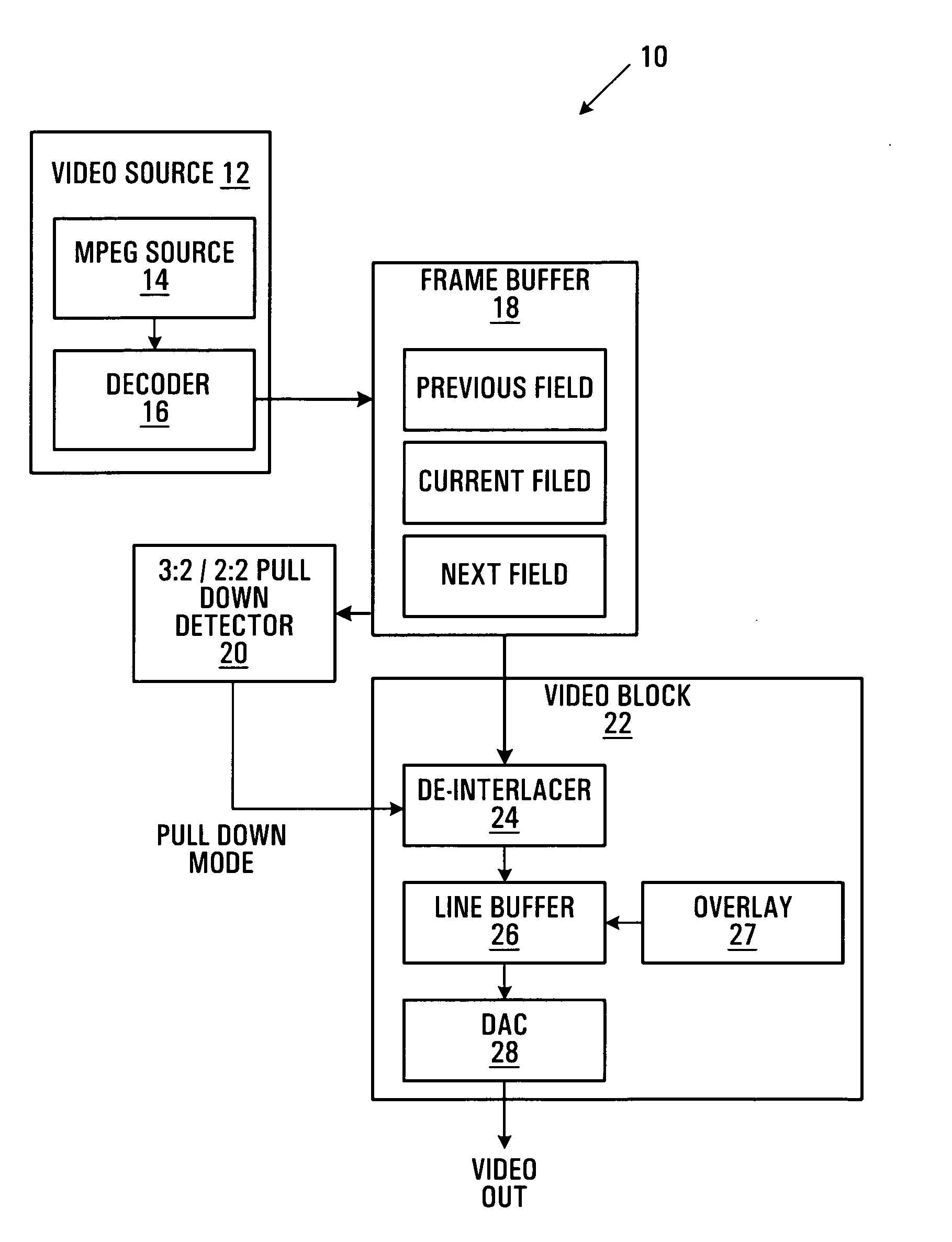
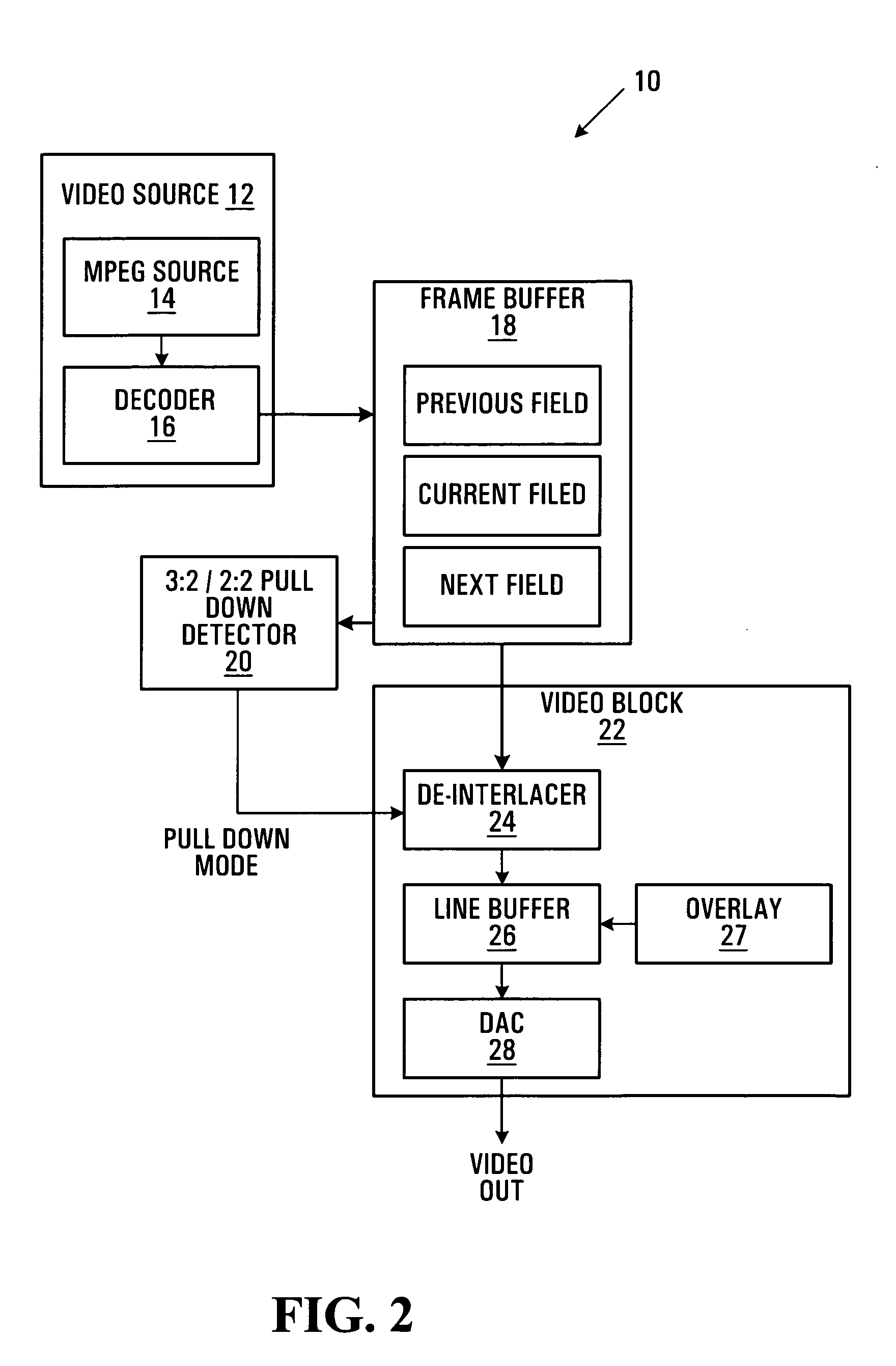
[0025]FIG. 2 illustrates a video device 10 for generating a progressive scan video output signal. Video device 10 includes a film mode (3:2 / 2:2 pulldown) sequence detector 20, exemplary of embodiments of the present invention. As illustrated, video device 10 includes a video source 12 of digitized video providing a sequence of video fields to a frame buffer 18.

[0026] In the embodiment of FIG. 2 video source 12 provides decoded video stored as MPEG 1 or 2 video originating with MPEG source 14. MPEG source 14 may, for example, be a source of MPEG encoded video, and may for example be a DVD, read by an appropriate reader. MPEG source 14 could similarly be a demodulated MPEG stream carried by a satellite or cable television signal, or digital television signal. Decoder 16 decodes the digital stream into rasterized video frames or fields. For example, for non-progressive (i.e. interlaced) sources decoder 16 decodes interlaced video into odd and even fields and provides these fields to f...


PUM


Abstract

A film mode detector detects film mode of a series of fields of video by comparing pixels in a field adjacent the current field, with corresponding pixels directly above and directly below the pixels in an adjacent field. The number of pixels in the adjacent in time to the current field having (or not having) a value approximately between values of the pixels above and below in the current field is assessed. Film mode for a current field may be detected by monitoring the assessment from field to field. Alternatively or additionally, the detector may detect film mode by assessing for each current field, whether a relatively large or relatively small number of pixels in the immediately previous field have values outside a specified distance of values of a corresponding pixel in the immediately subsequent field, for at least a portion of the immediately previous and subsequent fields. Again, film mode may be detected by monitoring this second assessment from field to field.

Description

FIELD OF THE INVENTION [0001] The present invention relates generally to video devices and more particularly to a film mode (3:2 / 2:2 pulldown) detection circuit. BACKGROUND OF THE INVENTION [0002] Analog television in North America is broadcast in accordance with the NTSC standard. The NTSC standard calls for about sixty (exactly 59.94) interlaced fields to be presented each second. Each field represents one half the lines or rows of a video frame. Fields are typically referred to as odd and even, with odd field containing odd lines of each frame, and even fields containing even lines of each frame. Thus, in one field half a frame is presented and in the next field the other half of the frame is presented. The human eye perceives the two fields as a single frame. [0003] Most cinema films, on the other hand, are filmed at a rate of twenty-four frames per second. Accordingly, cinema films are converted for viewing on analog NTSC television using a process known as 3:2 pulldown. This c...

Claims


Application Information

Patent Timeline
Patent Type & Authority Applications(United States)
IPC IPC(8): H04N5/44H04N7/01
CPCH04N7/012H04N7/0115
Inventor DOSWALD, DANIELNG, PATRICK CHE WA
Owner AVAGO TECH INT SALES PTE LTD
Why Eureka
Try Eureka