Head stack assembly and manufacturing thereof

a stack assembly and stack technology, applied in the direction of head support, record information storage, instruments, etc., can solve the problems of difficult creation, large trouble in the manufacturing process, and too limited corner space, so as to achieve convenient and safe manufacturing

Inactive Publication Date: 2005-11-03
SAE MAGNETICS (HK) LTD
View PDF10 Cites 24 Cited by
  • Summary
  • Abstract
  • Description
  • Claims
  • Application Information

AI Technical Summary

Benefits of technology

[0010] A main feature of the present invention is to provide a convenien

Problems solved by technology

However, referring to FIG. 2(b), because the traditional manufacturing method of the HSA requires the connection balls 15 to be placed on the inside corner formed by the suspension flexure cables 20 and the FPCA 9, it causes a great trouble with the manufacturing process for the following reasons: firstly, the connection balls 15 are difficult to create and the above-mentioned corner is too limited a space to operate therein.
In addition, the alignment of the connecting pads 16 of the FPCA 9 and the bonding pads 19 of the suspension flexure cables 20 and their electrical coupling is also a great challenge which will adversely affect the quality of the HSA and the efficiency of the manufacturing process, and increase the tooling and equipment cost

Method used


Image

  • Head stack assembly and manufacturing thereof
  • Head stack assembly and manufacturing thereof
  • Head stack assembly and manufacturing thereof

Examples


Embodiment Construction

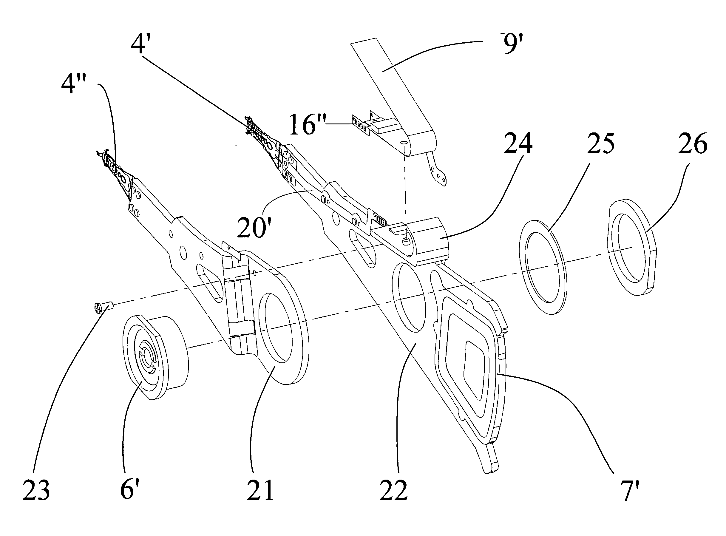
[0034] Referring now to the drawings in detail, FIG. 4 shows a HSA of a disk drive unit according to an embodiment of the present invention. The HSA comprises a first head arm assembly (HAA) 22 and a second HAA 21 coupled to the first HAA 22 by securing means (not labeled). In an embodiment of the present invention, see FIG. 5, the securing means comprises a pivot 6′, a washer 25, a nut 26 and a screw 23.

[0035] Referring to FIG. 6, the first HAA 22 comprises a first head gimbal assembly having a first suspension 4′ and a first slider 3′ (see FIG. 9), a first drive arm 5′ to be connected with to the first suspension 4′, a bracket 24 positioned on one side of the first drive arm 5′, and a voice coil 7′ embedded in the first drive arm 5′ for controlling the motion of the first drive arm 5′. In an embodiment of the invention, the bracket 24, the first suspension 4′, and the voice coil 7′ are overmolded onto the first drive arm 5′.

[0036] In the present invention, with reference to FIGS...


PUM


Abstract

A method for manufacturing a head stack assembly (HSA) of a disk drive unit includes including the steps of: forming a head arm assembly (HAA) having an overmolded suspension flexure cable thereon and a flexible printed circuit assembly; and bonding the suspension flexure cable with the flexible printed circuit assembly by conductive epoxy to attain an electrical connection therebetween. In the invention, the conductive epoxy is preferably anisotropic conductive film. Forming the head arm assembly further comprises forming a drive arm, and overmolding a suspension, a bracket, and a voice coil thereonto. Also, the method may further include a step of forming another HAA as a part of the HSA. In addition, a structure of the HSA is also disclosed in the present invention.

Description

FIELD OF THE INVENTION [0001] The present invention relates to disk drive units and manufacturing method thereof, and more particularly to a manufacturing method of a HSA (head stack assembly). BACKGROUND OF THE INVENTION [0002] Disk drives are information storage devices that use magnetic media to store data. Referring to FIG. 1, a typical disk drive in prior art comprises a drive arm 5, a head gimbal assembly (HGA) 4 with a slider 3 being coupled to the drive arm 5 (the drive arm and the HGA with the slider also known as head stack assembly (HSA)), a magnetic disk 1 mounted on a spindle motor 2 which causes the magnetic disk 1 to spin, and a disk drive base plate 13 to enclose the above-mentioned components. The slider 3 flies over the surface of the magnetic disk 1 at a high velocity and is positioned radially by a voice coil 7 embedded (e.g. by epoxy potting or overmolding) in a fantail spacer 8 to read data from or write data to concentric data tracks on the magnetic disk 1. Ge...

Claims


Application Information

Patent Timeline
IPC IPC(8): G11B5/48G11B5/55H05K3/32H05K3/36
CPCG11B5/4846H05K3/361H05K3/323G11B5/5569G11B5/4833G11B5/486H05K1/028H05K2201/053H05K2201/055
Inventor KAMIGAMA, TAKEHIROHO, YIU SINGCHEN, CANHUA
Owner SAE MAGNETICS (HK) LTD
Why Eureka
Try Eureka