Fluid Dynamic Pressure Bearing and Recording Disk Drive Device Comprising the Same

Inactive Publication Date: 2005-11-03
NIDEC CORP
View PDF3 Cites 19 Cited by
  • Summary
  • Abstract
  • Description
  • Claims
  • Application Information

AI Technical Summary

Benefits of technology

[0036] With this groove, an inside and an outside of the radial dynamic pressure bearing are connected and the groove functions as a reservoir for supplying the dynamic pressure generating fluid to the radial dynamic pressure bearing. Moreover, this groove parallel to the axial direction prevents pressure of the dynamic pressure generating fluid from becoming negative pressure in the radial dynamic pressure bearing.
[0037] The sleeve used for the inv

Problems solved by technology

However, if the motor is made thin and a radial length of the radial dynamic pressure bearing is reduced, it is difficult to arrange the herringbone grooves in a plurality of rows in the radial direction because of working constraints.
However, with a row of grooves, the moment stiffness is insufficient and it is difficult to

Method used


Image

  • Fluid Dynamic Pressure Bearing and Recording Disk Drive Device Comprising the Same
  • Fluid Dynamic Pressure Bearing and Recording Disk Drive Device Comprising the Same
  • Fluid Dynamic Pressure Bearing and Recording Disk Drive Device Comprising the Same

Examples


Example

First Embodiment

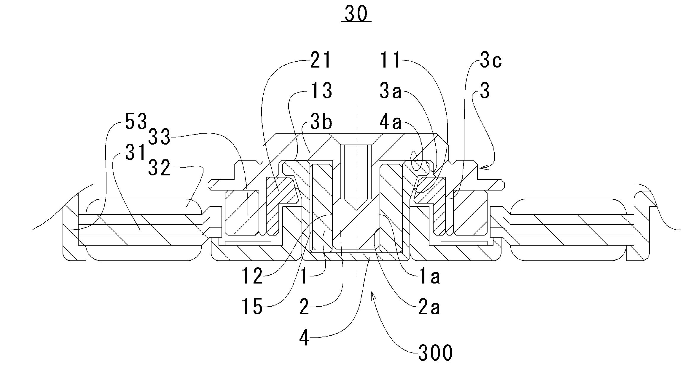
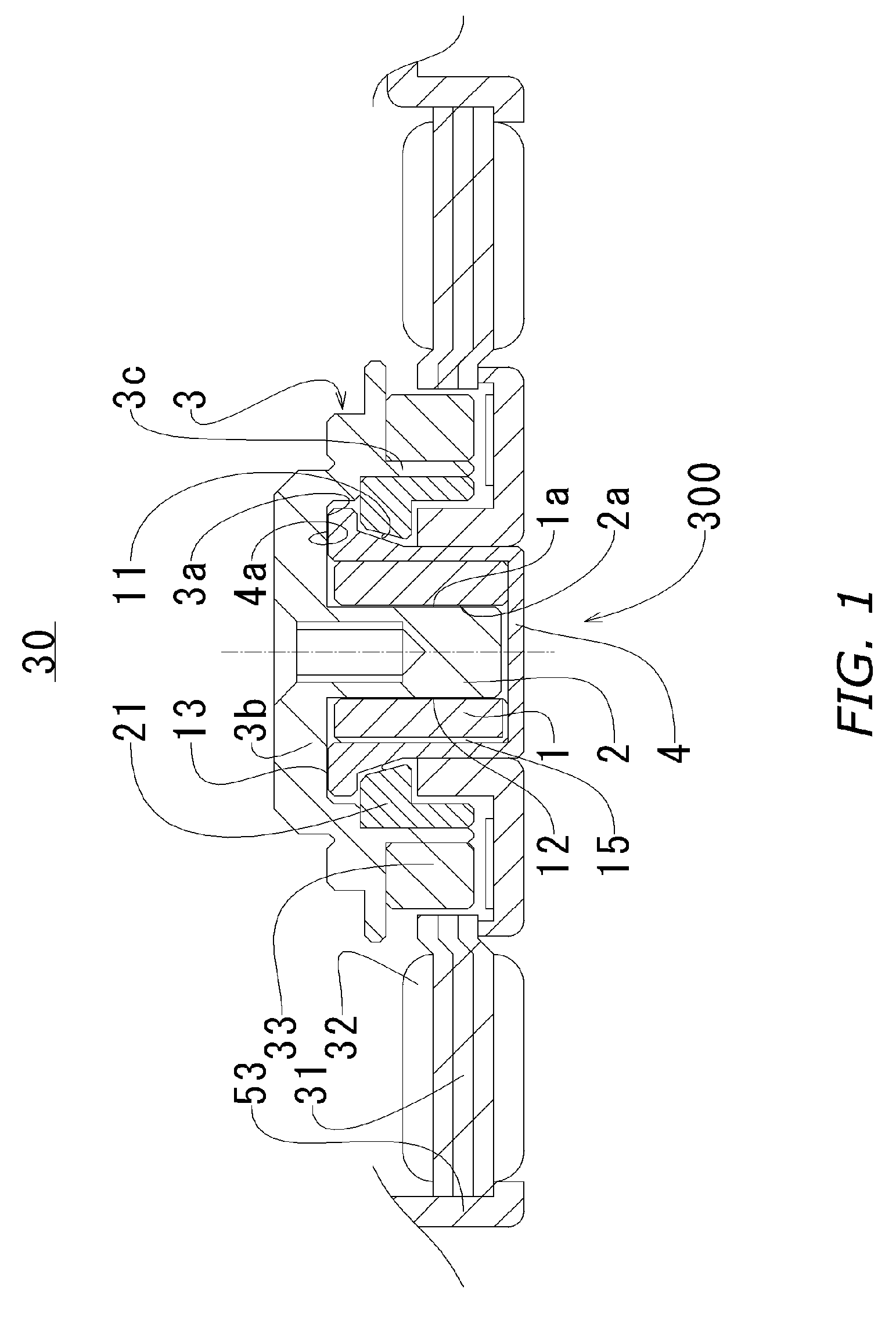
[0052]FIG. 1 is a sectional view of a dynamic pressure bearing 10 according to the first embodiment in which the invention is carried out and a spindle motor in which the bearing 10 is used. Although the dynamic pressure bearing 10 of the present embodiment is used in the spindle motor, description of a structure of a rotary drive portion will be omitted. For this rotary drive portion, a structure of a conventionally-used DC motor can be employed.

[0053] (1-1) Structure

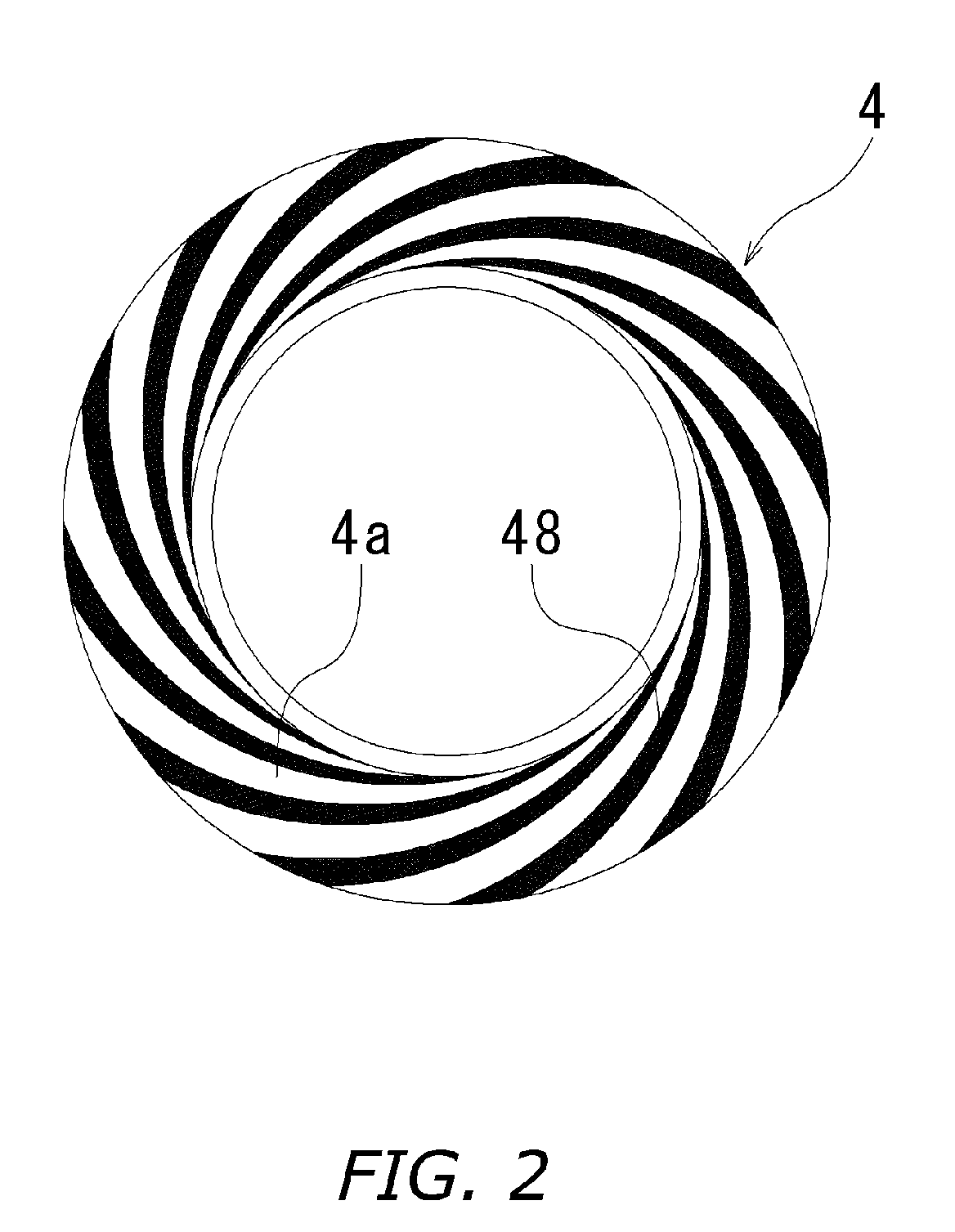
[0054] The dynamic pressure bearing 10 of the invention is formed of a substantially columnar shaft 1, a substantially cylindrical sleeve 2, a substantially cup-shaped bearing housing 4 positioned radially outside the sleeve 2 and covering the sleeve 2, and a rotor hub 3 having a top portion 3b radially extending from an upper end portion of the shaft 1. The sleeve 2 is formed of a sintered porous metal. The bearing housing 4 is made of aluminum, stainless steel, brass, resin, and the like. The shaft...

Example

Second Embodiment

[0082]FIG. 7 is a sectional view of a dynamic pressure bearing100 according to the second embodiment in which the present invention is carried out.

[0083] (2-1) Structure

[0084] The dynamic pressure bearing 100 of the present embodiment includes, like the first embodiment, a substantially columnar shaft 101, a substantially cylindrical sleeve 102, a bearing housing 104 having a cylindrical portion positioned radially outside the sleeve 102, and a rotor hub 103 having a top portion radially extending from an upper end portion of the shaft 101. An upper end portion of the cylindrical portion of the bearing housing 104 extends radially inward so that an upper end face of the sleeve 102 comes in contact with the upper end portion and the upper end portion is formed with an annular portion 104a having a smaller inside diameter than an outer peripheral face 101a of the shaft 101. The shaft 101 has a circumferential recessed portion 101c having a smaller diameter than an ...

Example

Third Embodiment

[0092]FIG. 8 is a sectional view of a dynamic pressure bearing 200 according to the third embodiment in which the present invention is carried out.

[0093] (3-1) Structure

[0094] The dynamic pressure bearing 200 of the present embodiment is formed of a substantially columnar shaft 201, a substantially cylindrical sleeve 202, a first thrust bushing 206A fixed to the shaft 201 and having a thrust plane 206Aa opposed to an upper end face 202b of the sleeve 202, a second thrust bushing 206B fixed to the shaft 201 and having a thrust plane 206Ba opposed to a lower end face 202c of the sleeve 202, a rotor hub 203 fitted from radially outside with the sleeve 202, a first sealing member 207A attached to the rotor hub 203 and positioned on an axial upper side of the first thrust bushing 206A, and a second sealing member 207B attached to the rotor hub 203 and positioned on an axial lower side of the second thrust bushing 206B.

[0095] (3-2) Structure of Dynamic Pressure Bearing...


PUM


Abstract

In a radial minute gap between a substantially columnar shaft and an inner peripheral face of a substantially cylindrical sleeve, oil is retained and a radial dynamic pressure bearing is formed. A plurality of recessed portions are arranged in a circumferential direction on at least one of an outer peripheral face of the shaft and the inner peripheral face of the sleeve and a first hill portion is provided to an axial end portion of each the recessed portion. Thus, it is possible to achieve a dynamic pressure bearing with which sufficient radial shaft support can be obtained in spite of a short axial length.

Description

BACKGROUND OF THE INVENTION [0001] 1. Field of the Invention [0002] The present invention relates to a small and thin dynamic pressure bearing, a spindle motor formed by using the dynamic pressure bearing, and a recording disk drive device formed by using the spindle motor. [0003] 2. Background Art [0004] In recent years, recording disk drive devices including a hard disk drive have been miniaturized more than ever and are used not only in computer equipment, which was a conventional use of the devices, but also in home audiovisual equipment and portable equipment. Since the disk drive device is miniaturized, a spindle motor for rotating the recording disk has to be also miniaturized and made thinner. [0005] In the spindle motor for rotating the recording disk, a fluid dynamic pressure bearing is used to meet demands for quietness and long life. In order to support radial loads, substantially V-shaped herringbone grooves are formed in general. By arranging herringbone grooves in two...

Claims


Application Information

Patent Timeline
IPC IPC(8): F16C17/10F16C17/02F16C19/00F16C33/10G11B19/20H02K7/08H02K21/22
CPCF16C17/107F16C33/103F16C2370/12G11B19/2018H02K7/085F16C33/107
Inventor MURATA, ITSUOOSAWA, HARUSHIGEFENG, MINGTOKUNAGA, SHINYA
Owner NIDEC CORP
Why Eureka
Try Eureka