Apparatus for machining a cylinder bore surface and method of machining the cylinder bore surface using the apparatus

a technology for machining cylinders and cylinder bores, which is applied in the direction of manufacturing tools, portable drilling machines, transportation and packaging, etc., can solve the problems of increasing the inability to improve productivity, and the inability to use a masking sheet disposable, so as to improve the productivity, increase the cost of a masking sheet material and adhesives, and increase the total machining time

Inactive Publication Date: 2005-11-03
NISSAN MOTOR CO LTD
View PDF8 Cites 19 Cited by
  • Summary
  • Abstract
  • Description
  • Claims
  • Application Information

AI Technical Summary

Benefits of technology

[0004] It is an object of the present invention to provide an apparatus for machining a cylinder bore surface of a workpiece and a method of machining the cylinder bore surface using the apparatus, which are capable of uniformly forming microscopic recesses on the cylinder bore surface, reducing the total machining time, improving the productivity and saving the production costs such as the facility cost and costs for ensuring the facility-occupying floor space.

Problems solved by technology

This causes increase in total machining time, facility cost and facility-occupying floor space.
Particularly, in the shot blasting process, the operations of attaching and removing the masking sheet are inevitably required, thereby failing to improve the productivity.
In addition, the use of the disposable masking sheet requires increased costs for a masking sheet material and adhesives, and the costs of forming the through-holes in the masking sheet each time upon conducting the microscopic recess-forming process.
This results in significant increase in production cost for production of the cylinder bore surface having the microscopic recesses.
Further, it is difficult to uniformly form the microscopic recesses on the cylinder bore surface by shot blasting.

Method used


Image

  • Apparatus for machining a cylinder bore surface and method of machining the cylinder bore surface using the apparatus
  • Apparatus for machining a cylinder bore surface and method of machining the cylinder bore surface using the apparatus
  • Apparatus for machining a cylinder bore surface and method of machining the cylinder bore surface using the apparatus

Examples


first embodiment

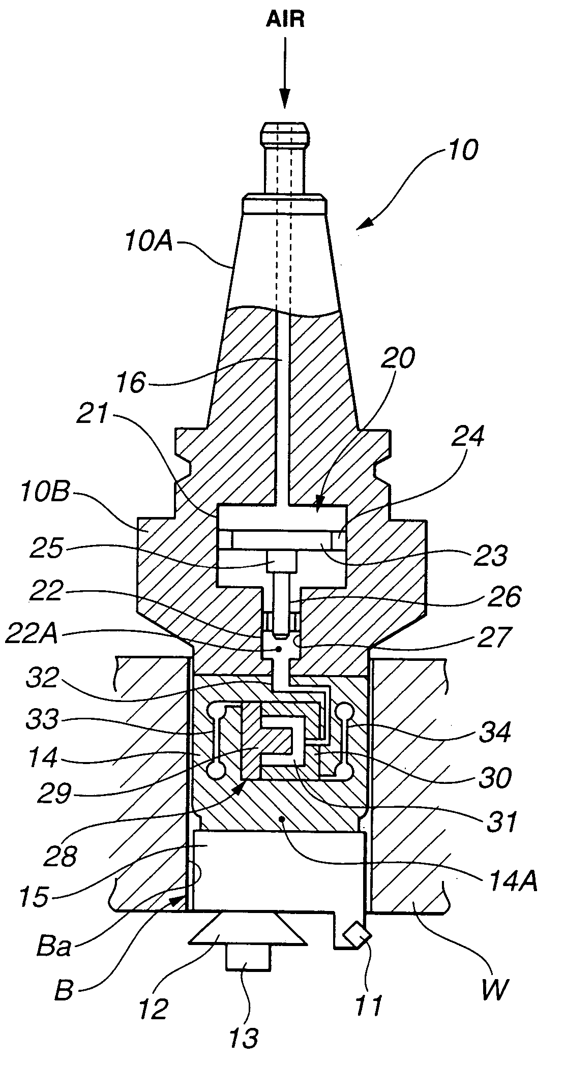
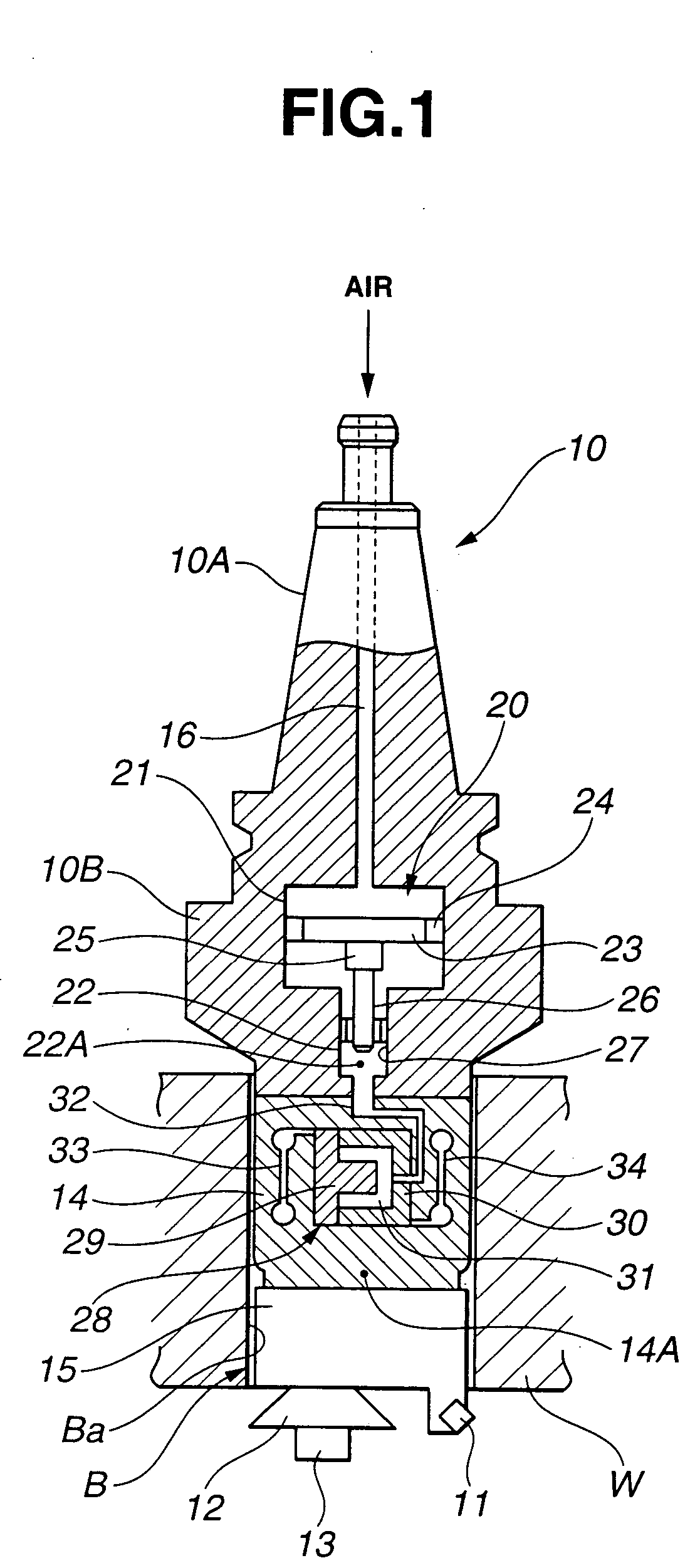
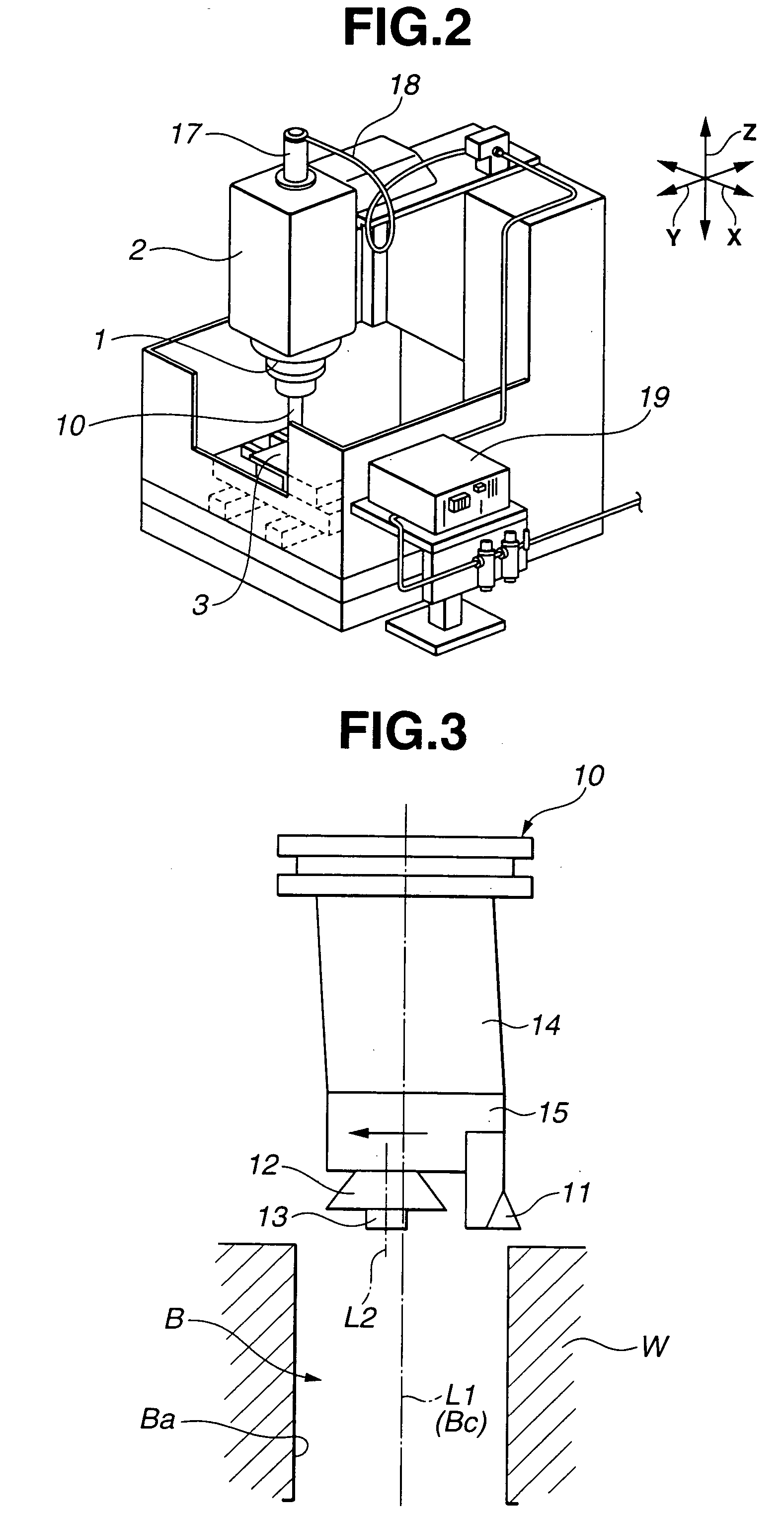
[0021] Referring to FIG. 2, there is shown a machine tool to which the apparatus of the present invention can be applied. The machine tool includes main shaft 1 projecting from main shaft head 2, and support platform 3 disposed below main shaft head 2. Workpiece W is retained on support platform 3. Tool holder 10 is mounted to main shaft 1. Main shaft head 2 is moveable in vertical direction Z as shown in FIG. 2. Support platform 3 is moveable in two directions X and Y, as shown in FIG. 2, perpendicular to each other in a horizontal plane and perpendicular to direction Z. Tool holder 10 mounted to main shaft 1 is driven to rotate about rotation axis L1 together with main shaft 1. Tool holder 10 is detachable from main shaft 1 using an automatic tool interchange device, not shown.

[0022] Referring back to FIG. 1, tool holder 10 supports boring blade 11 for boring inner circumferential surface Ba of cylinder block W to enlarge cylinder bore B, and form roller 12 for forming microscopic...

third embodiment

[0053] The thus-constructed apparatus of the third embodiment is operated in the following manner. First, cylinder block W is set on support platform 3 in such a manner that rotation axis L1 of tool holder 100 and central axis Bc of cylinder bore B are aligned with each other. Next, tool holder 100 and cylinder block W are relatively moved in an axial direction such that tool holder 100 is inserted into cylinder bore B. Specifically, main shaft head 2 with tool holder 100 is downwardly moved so that form roller 111 held on tool holder 100 is inserted into cylinder bore B.

[0054] Driver 10D in adapter 10C is actuated to move form roller 111 in the radial direction thereof until the outer circumferential portion of form roller 111 is brought into contact with inner circumferential surface Ba of cylinder block W. Driver 10D is then kept actuated until a load applied by load applier 120 and detected by load detector 121 reaches a predetermined value. The load is variably applied to form ...


PUM

PropertyMeasurementUnit
diameteraaaaaaaaaa
pressureaaaaaaaaaa
air pressureaaaaaaaaaa

Abstract

An apparatus for machining a circumferential surface defining a cylindrical bore of a workpiece, the apparatus including a tool holder rotatable about a first rotation axis, and a form roller supported on the tool holder so as to be rotatable about a second rotation axis parallel to a central axis of the cylindrical bore of the workpiece. The form roller has a diameter smaller than a diameter of the cylindrical bore of the workpiece and is adapted for forming a plurality of microscopic recesses on the circumferential surface defining the cylindrical bore of the workpiece.

Description

BACKGROUND OF THE INVENTION [0001] The present invention relates to an apparatus for machining an inner circumferential surface of a workpiece which defines a cylindrical bore, for instance, a cylinder bore surface of a cylinder block of an engine for automobiles, and a method of machining the inner circumferential surface using the apparatus. More specifically, the present invention relates to an apparatus for use upon boring the inner circumferential surface of the workpiece and forming microscopic recesses as oil retention portions on the inner circumferential surface in order to reduce friction on the inner circumferential surface, and relates to a method of machining the inner circumferential surface using the apparatus. [0002] Conventionally, upon boring a cylinder bore surface of a cylinder block of an engine and forming a plurality of microscopic recesses on the cylinder bore surface, the cylinder bore surface is subjected to boring and honing and then subjected to shot blas...

Claims


Application Information

Patent Timeline
Patent Type & Authority Applications(United States)
IPC IPC(8): B21C37/20B21C37/30B23B27/24B23B29/034B24B1/00B24B39/02
CPCB21C37/207Y10T82/125B23B27/24B23B29/03439B23B29/0346B23B2215/24B23B2260/09B23B2260/108B23B2260/128B23B2260/136B23B2270/025B23B2270/027B23B2270/24B24B39/02Y10T408/65Y10T82/12Y10T82/10Y10T408/854B21C37/30
Inventor TAKASHIMA, KAZUHIKONAKAYAMA, TATSUOMIOTA, MINORUWAKUDA, MANABU
Owner NISSAN MOTOR CO LTD
Why Eureka
Try Eureka