Relative humidity sensor enclosed with ceramic heater

a technology of relative humidity and ceramic heater, applied in the field of sensor methods and systems, can solve the problems of erroneous readings, dissipation effect, and elements utilized as resistive components, and achieve the effect of reducing the volume of water

Inactive Publication Date: 2005-11-10
HONEYWELL INT INC
View PDF26 Cites 30 Cited by
  • Summary
  • Abstract
  • Description
  • Claims
  • Application Information

AI Technical Summary

Benefits of technology

[0021] An additional heating element can be bonded to a base of the RH sensor. The thin substrate material can be configured from a polymide polymer, such as Kapton® material. Additionally, a filter material can be located at vent openings in the RH sensor housing to create a relatively large space of stagnant air adjacent to the RH sensor. The filter material may be a hydrophobic material such as Goretex® which can limit the size of water droplets which pass through and therefore reduce the volume of water entering the sensor housing and needing to be evaporated.

Problems solved by technology

With respect to humidity sensors, for example, providing suitable instruments for the measurement of relative humidity (RH) over wide RH ranges (e.g., 1%-100%) continues to be a challenge.
It has been found, however, that elements utilized as resistive components suffer from the disadvantage that there is an inherent dissipation effect caused by the dissipation of heat due to the current flow in the elements necessary to make a resistance measurement.
The result is erroneous readings, among other problems.
In addition, there can also be inaccuracy incurred at high relative humidity values where high water content causes problems due to excessive stress and the resulting mechanical shifts in the components of the element.
A limitation of humidity sensor is the relative humidity (RH) can be measured up to 100% RH above which the sensor reaches saturation.
At levels higher than 100% RH, minute water droplets are formed in suspension (fog, a.k.a. two-phase flow) and the sensor may fail to operate.

Method used


Image

  • Relative humidity sensor enclosed with ceramic heater
  • Relative humidity sensor enclosed with ceramic heater
  • Relative humidity sensor enclosed with ceramic heater

Examples


first embodiment

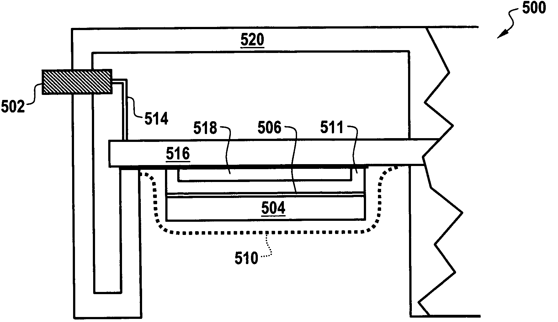
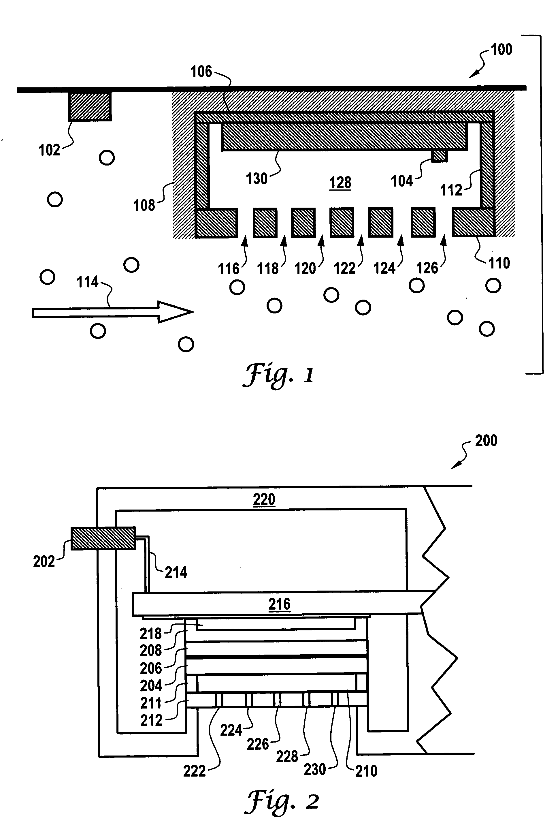
[0058] Based on the foregoing, it can be appreciated that varying sensor systems and methods are disclosed herein. In accordance with a first embodiment, an RH sensor can be associated with one or more heating elements, wherein a perimeter of the RH sensor is surrounded with a relatively conductive material. A thin substrate material can surround and laminate the heating element, such that the heating element is perforated to permit humid air to pass through the heating element and wherein the heating element is assembled slightly offset from a surface of the RH sensor.

[0059] Air that is saturated with two phase flow of water vapor and minute droplets can then pass through and be heated by the heating element in order to evaporate water droplets associated with the water vapor to thereby reduce relative humidity to a measurable level. An additional heating element can be bonded to a base of the RH sensor. The thin substrate material can be configured from a polymide polymer, such as...

second embodiment

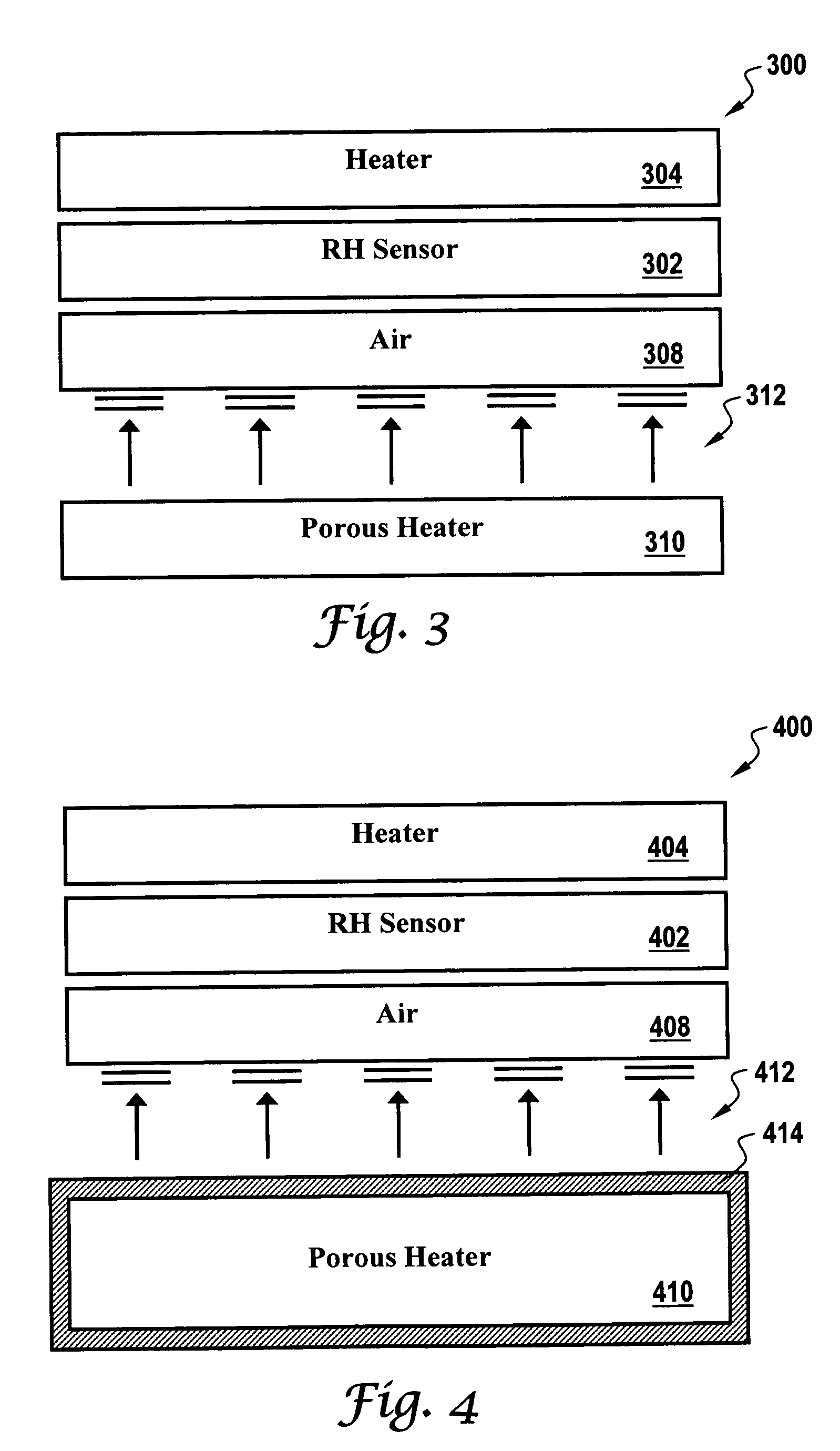
[0060] In accordance with a second embodiment, an RH sensor can be associated with one or more ceramic heating element, wherein a perimeter of the RH sensor is surrounded with a relatively conductive material. A resistive material can surround and laminate the ceramic heating element. The ceramic heating element can be configured from a porous material, wherein air that is saturated with water vapor passes through and is heated by the ceramic heating element in order to evaporate water droplets associated with the water vapor to thereby reduce relative humidity to a measurable level. One or more other heating elements can be bonded to the base of the RH sensor. The porous material forming the ceramic heating element can be formed by providing a plurality of laser drilled holes to create porosity thereof. Additionally, a filter material can be located slightly offset from the RH sensor to create a thin space of stagnant air adjacent to the RH sensor.

third embodiment

[0061] In accordance with a third embodiment, an RH sensor can be associated with one or more heating elements, wherein the RH sensor is surrounded by a sheet of porous resistive material in a woven or perforated pattern or state. The porous heating element can be configured to permit humid air to pass through the porous heating element. The porous heating element can be further assembled slightly offset from a surface of the RH sensor, wherein air that is saturated with water vapor passes through and is heated by the porous heating element in order to evaporate water droplets thereof to thereby reduce relative humidity to a measurable level. Additionally, a flat heating element can be bonded to the base of the RH sensor to conduct heat and insure uniform heating about the RH sensor. The porous resistive material can be formed from material such as tantalum or nichrome. A filter material can also be located slightly offset from the RH sensor to create a thin space of stagnant air ad...


PUM

PropertyMeasurementUnit
RHaaaaaaaaaa
RHaaaaaaaaaa
humidityaaaaaaaaaa

Abstract

Sensor systems and methods are disclosed herein. A relative humidity sensor can be associated with one or more ceramic heating elements configured from a porous material. In general, a perimeter of the relative humidity sensor is surrounded with a relatively conductive material. A resistive material surrounds one or more of the ceramic heating elements, such that air that is saturated with water vapor passes through the porous material of the ceramic heating element(s). Water vapor can therefore be heated by the ceramic heating element(s) in order to evaporate water droplets associated with the water vapor and thereby reduce relative humidity to a measurable level. The porous material of the ceramic heating element(s) can be provided via a plurality of laser drilled holes to create such porosity.

Description

REFERENCE TO RELATED APPLICATION [0001] This patent application claims priority under 35 U.S.C. § 119(e) to provisional patent application Ser. No. 60 / 568,591 entitled “Sensor Methods and Systems,” which was filed on May 6, 2004, the disclosure of which is incorporated herein by reference.GOVERNMENT INTERESTS [0002] The United States government may have rights in the invention described herein made in the performance of work under Department of Energy (DOE) Cooperative Agreement DE-FC36-02AL67615.TECHNICAL FIELD [0003] Embodiments are generally related to sensor methods and systems. Embodiments are also related to humidity sensors and moisture sensing elements thereof, flow sensors, pressure sensors, thermal sensors and temperatures sensors. Embodiments are additionally related to sensors utilized in fuel cell systems, such as, for example, PEM fuel cell applications. BACKGROUND OF THE INVENTION [0004] Humidity sensors, flow sensors, pressure sensors and temperatures sensors and the...

Claims


Application Information

Patent Timeline
Patent Type & Authority Applications(United States)
IPC IPC(8): G01N25/56G01N25/60G01N27/00G01N27/12G01N27/22G01N27/60
CPCG01N25/60
Inventor SPELDRICH, JAMIE W.FARREY, MICHAEL P.
Owner HONEYWELL INT INC
Why Eureka
Try Eureka