Voltage current conversion device and light emitting device

Inactive Publication Date: 2005-11-10
CANON KK
View PDF12 Cites 0 Cited by
  • Summary
  • Abstract
  • Description
  • Claims
  • Application Information

AI Technical Summary

Benefits of technology

[0022] According to the present invention, even in case the self-bias period of the voltage/current conversion transistor which decides an output current is a short period of time, the output current can be almost completely shut off for the zero setting of an input voltage. Consequently, even in case an element reacting to a micro current is current-driven,

Problems solved by technology

That is, the current supply to the pixel is completely shut off, and the bl

Method used


Image

  • Voltage current conversion device and light emitting device
  • Voltage current conversion device and light emitting device
  • Voltage current conversion device and light emitting device

Examples


Example

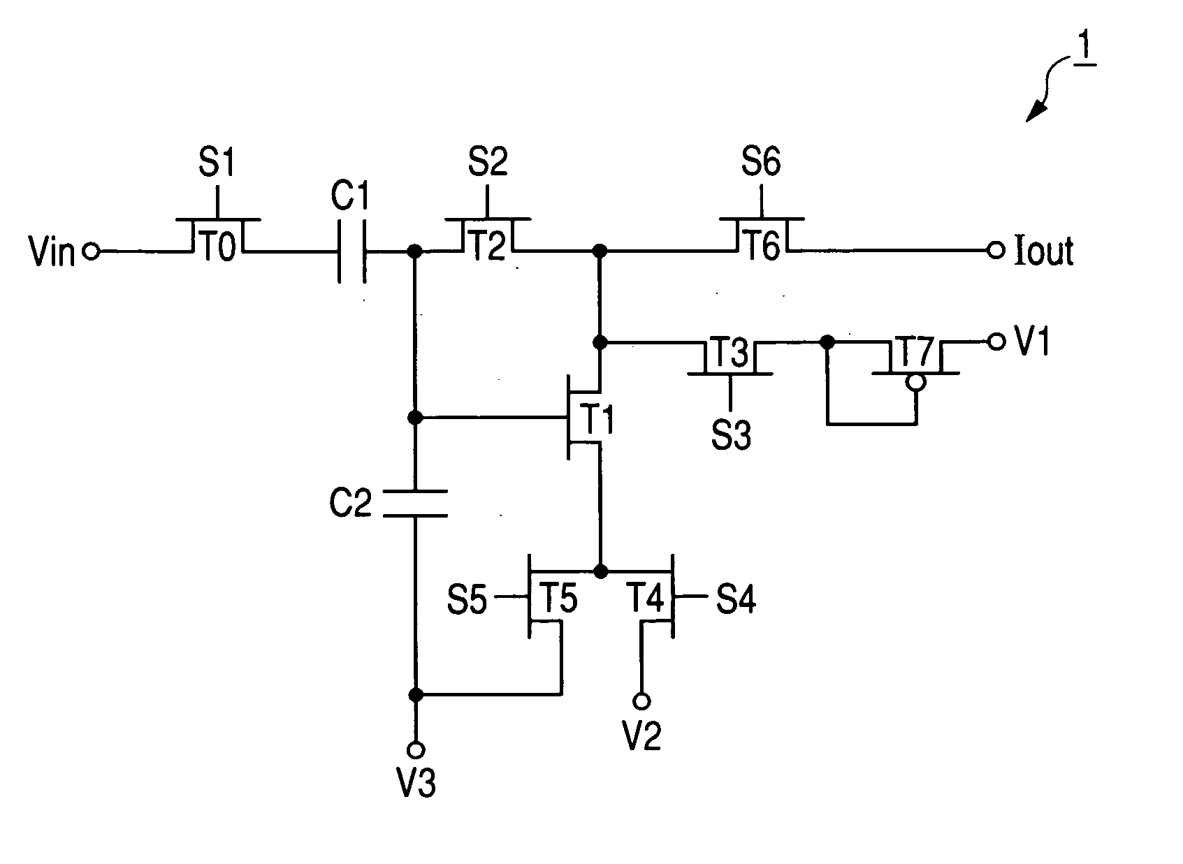
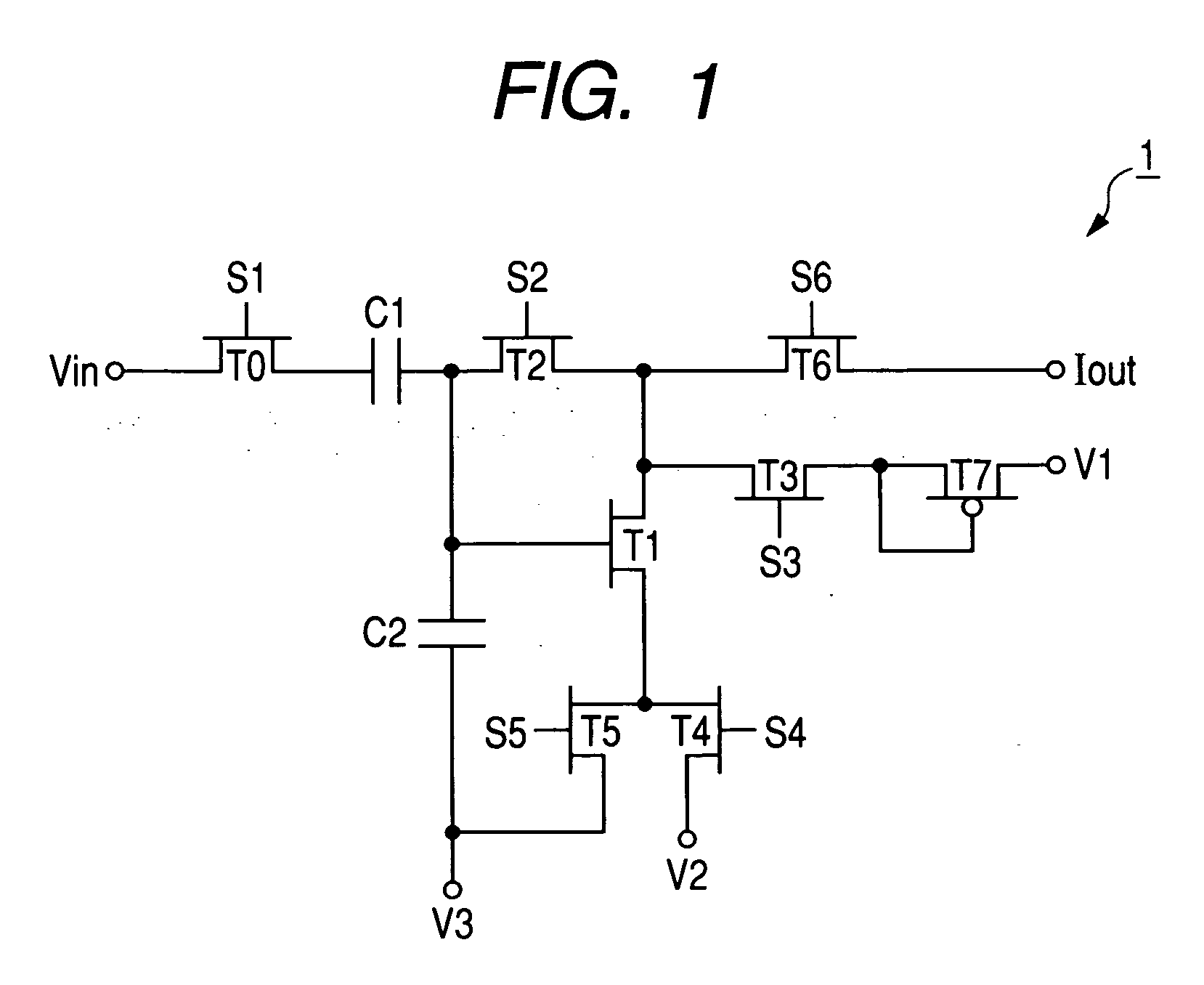
[0030] A circuit constitution of a preferred embodiment of the voltage current conversion device of the present invention is shown in FIG. 1. In the drawing, reference characters T0 to T6 denote a n-type transistor, respectively, reference character T7 denote a p-type transistor, reference characters C1 and C2 denote first and second capacitors, respectively, reference characters S1 to S6 denote a independent control signal, respectively, reference characters V1 to V3 denote first to third potentials, which serves also as a potential source which supplies these potentials, reference character Vin denotes an input terminal to which an input voltage is applied, and reference character Iout denotes an output terminal to which an output current is supplied.

[0031] The voltage current conversion device of FIG. 1, comprising: [0032] a voltage / current conversion transistor T1 comprising a gate for receiving a voltage signal inputted from an input terminal Vin, a drain for outputting a curr...


PUM


Abstract

In case an input voltage is zero, to sufficiently shut off an output current, a source side of a first transistor T1 is connected to the drains of fourth and fifth transistors T4 and T5, and during a self-bias period of the first transistor T1, a source of the first transistor T1 is made a second potential through the fourth transistor T4, and in a gate potential setting period of the first transistor T1 by an input voltage Vin after the completion of the self-bias period, the source of the first transistor T1 is made a third potential through the fifth transistor T5.

Description

BACKGROUND OF THE INVENTION [0001] 1. Field of the Invention [0002] The present invention relates to a voltage current conversion device used in a light emitting device such as an exposing apparatus of an electrophotographing system and a display device, and in particular, it relates to a voltage current conversion device preferably disposed in a signal transfer channel for providing a video signal which is a voltage signal to each pixel as a current signal. [0003] 2. Related Background Art [0004] As a light emitting device, a display device will be cited as an example. In recent years, in general, an organic electroluminescence (EL) display device, which is one of the Trendy flat display panels, includes a display device of the type in which luminous brightness of an organic EL element disposed in each pixel as a light emitting element is decided by a current value provided in a data signal source. In this type, a voltage current conversion device is disposed in the data signal sou...

Claims


Application Information

Patent Timeline
IPC IPC(8): G05F1/56H03D1/00
CPCG05F1/561
Inventor YUKI, OSAMUKONDO, SHIGEKINAKAJIMA, YOSHINORI
Owner CANON KK
Why Eureka
Try Eureka