Identifying red eye in digital camera images

a digital camera and red eye technology, applied in the field of digital image processing, can solve the problems of reducing the success rate of detecting red eye, requiring considerable processing, and requiring large processing time, and achieve the effect of effective detection

Inactive Publication Date: 2005-11-10
EASTMAN KODAK CO
View PDF6 Cites 22 Cited by
  • Summary
  • Abstract
  • Description
  • Claims
  • Application Information

AI Technical Summary

Benefits of technology

[0006] It is an object of the present invention to provide an improved, automatic, computationally efficient way to detect red eye in color digital images.
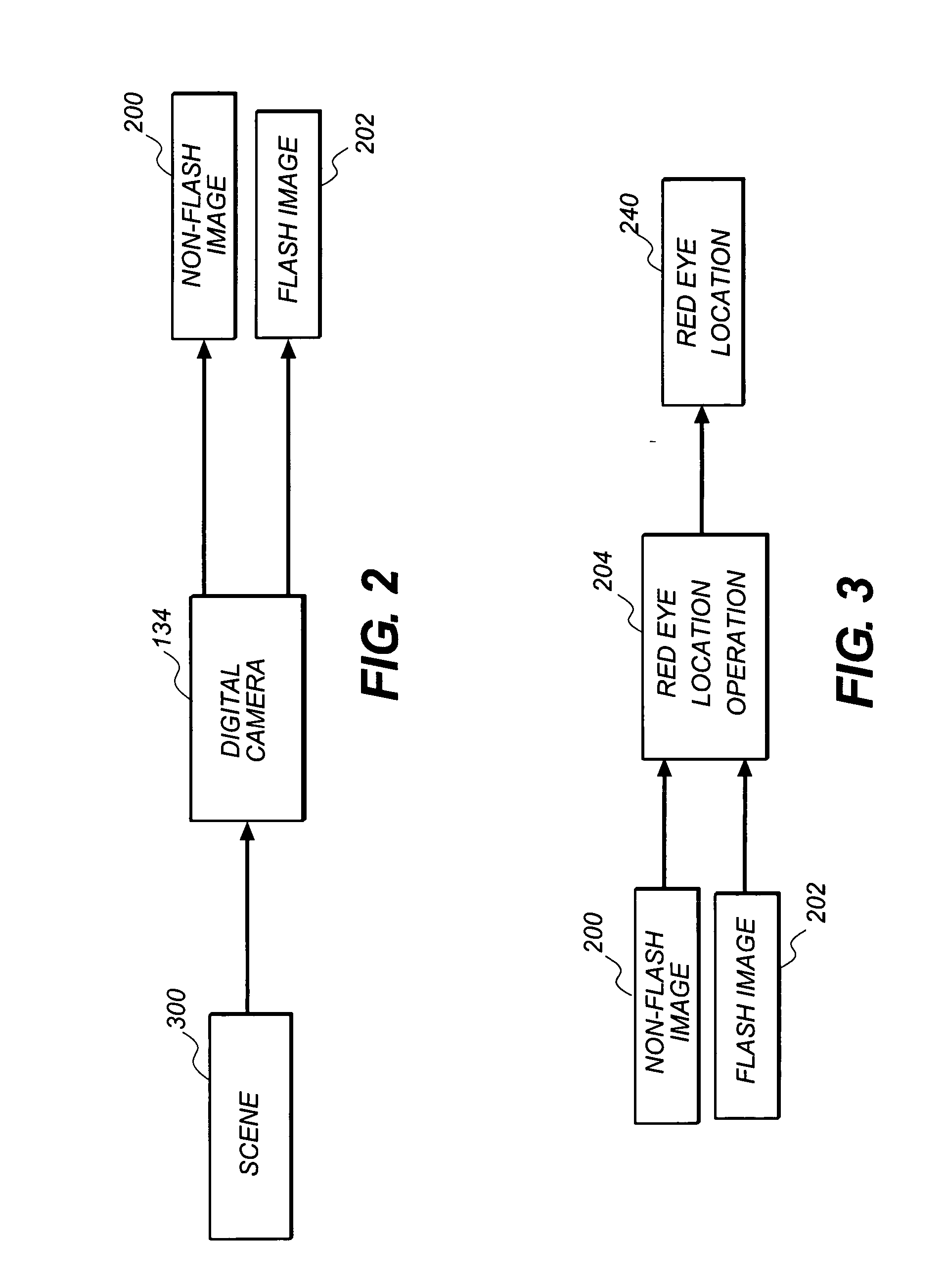
[0008] It has been found that by using a digital camera in a flash and non-flash mode to capture the same image of a scene that red eye can be more effectively detected by converting the primary-color space for the first and second digital images into the same chrominance channel, wherein the chrominance channel identifies a particular pair of colors and their relative intensity. Thereafter by calculating the difference between the chrominance channel of the image captured without flash and the chrominance channel of the image captured with flash; and responding to such differences to locate the position of red eyes within the first color digital image.

Problems solved by technology

A significant problem with existing red eye detection methods is that they require considerable processing to detect red eye.
These methods are often very computationally intensive and complex because they are not directly detecting red eye.
These methods often have reduced success rates for detecting red eye because the success is based on the accuracy with which they can infer the red eye location from other scene cues.
Another problem is that some of the methods require a pair of red eyes for detection.
Another problem is that some of the red eye detection methods require user intervention and are not fully automatic.
A significant problem with the red-eye reduction flash mode is the delay required between the pre-flash and the capture flash in order to appropriately reduce the red-eye effect.
The red-eye reduction flash mode also does not completely eliminate the red-eye effect.

Method used


Image

  • Identifying red eye in digital camera images
  • Identifying red eye in digital camera images
  • Identifying red eye in digital camera images

Examples


Embodiment Construction

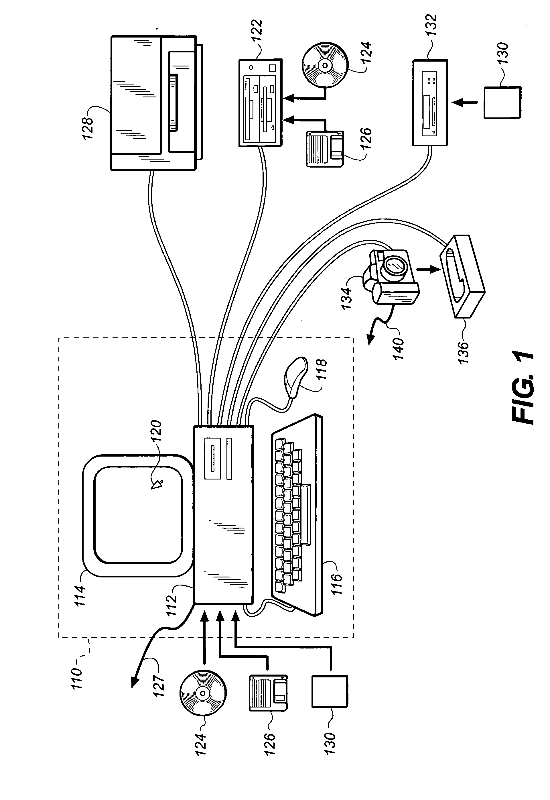
[0027] In the following description, a preferred embodiment of the present invention will be described in terms that would ordinarily be implemented as a software program. Those skilled in the art will readily recognize that the equivalent of such software may also be constructed in hardware. Because image manipulation algorithms and systems are well known, the present description will be directed in particular to algorithms and systems forming part of, or cooperating more directly with, the system and method in accordance with the present invention. Other aspects of such algorithms and systems, and hardware and / or software for producing and otherwise processing the image signals involved therewith, not specifically shown or described herein, may be selected from such systems, algorithms, components and elements known in the art. Given the system as described according to the invention in the following materials, software not specifically shown, suggested or described herein that is...


PUM


Abstract

A method of detecting red eye in a color digital image produced by a digital camera includes using the digital camera to capture two original color digital images of the same scene with the first color digital image being with flash and the second color digital image without flash and producing for each such digital images a plurality of pixels in the same primary-color space having red, green, and blue pixels; and converting the primary-color space for the first and second digital images into the same chrominance channel, wherein the chrominance channel identifies a particular pair of colors and their relative intensity. The method further includes calculating the difference between the chrominance channel of the image captured without flash and the chrominance channel of the image captured with flash; and responding to such differences to locate the position of red eyes within the first color digital image.

Description

CROSS REFERENCE TO RELATED APPLICATION [0001] Reference is made to commonly assigned U.S. patent application Ser. No. 10 / 792,079 filed Mar. 3, 2004, entitled “Correction Of Redeye Defects In Images Of Humans” by Andrew C. Gallagher et al, the disclosure of which is incorporated herein.FIELD OF THE INVENTION [0002] The invention relates generally to the field of digital image processing, and in particular to red eye detection in color digital images by digital cameras. BACKGROUND OF THE INVENTION [0003] Red eye in color digital images occurs when a flash illumination is reflected off a subject's retina and is captured by a camera. For humans this is usually a red color while for animals it is usually a red, green or yellow color. Many consumer cameras have a red-eye reduction flash mode that causes the subject's pupils to contract, thus reducing (but not eliminating) the red-eye effect. Other commercial methods have the user manually indicate the region of the red eye in the image to...

Claims


Application Information

Patent Timeline
IPC IPC(8): G06K9/00G06T5/00G06T7/00G06T7/40H04N1/62
CPCG06K9/0061G06T7/0081G06T7/0097G06T7/408G06T2207/10152G06T2207/20148G06T2207/10024G06T2207/30201G06T2207/30216H04N1/62H04N1/624G06T5/005G06T5/50G06T2207/20224G06T7/11G06T7/174G06T7/90G06T7/136G06V40/193G06T5/77
Inventor ENGE, AMY D.
Owner EASTMAN KODAK CO
Why Eureka
Try Eureka