
Selectable projector and imaging modes of display table

a technology of projector and display table, which is applied in the direction of roofs, television systems, instruments, etc., can solve the problems of homeowner's limited viewing of projected video images, the problem of mounting location, and the relatively high cost of the projector

Inactive Publication Date: 2005-11-10
MICROSOFT TECH LICENSING LLC
View PDF6 Cites 54 Cited by
  • Summary
  • Abstract
  • Description
  • Claims
  • Application Information

AI Technical Summary

Benefits of technology

[0009] More specifically, one aspect of the present invention is directed to a method for enabling a user to selectively operate a display table in one of two different modes, including a first mode in which a video image is projected on a display surface of the display table and a second mode in which the video image is projected onto a separate surface that is not part of the display table. The method includes the step of enabling the user to selectively change a projection light path for the video image between a first path that is used when operating the display table in the first mode, and a second path that is used when operating display table in the second mode. The video image is projected along the projection path selected by the user so that the video image is viewed on either the display surface or the separate surface, along either the first path or the second path that was selected by the user.
[0011] In a second embodiment, the user selectively changes the projection light path when selectively operating the display table in the second mode, by positioning a reflective surface to redirect the video image along the second path instead of along the first path. In this embodiment, it may be necessary for the user to move a panel of the display table out of the second path when operating the display table in the second mode, so that the video image is not prevented from reaching the separate surface by the panel.
[0013] Another aspect of the present invention is directed to a system that enables a user to selectively determine where a video image is to be projected. The system includes a display surface, and a projector, both of which are supported by a housing. The projector projects a video image along a light path. Means are included for enabling a user to change the system between a first mode and a second mode of operation by altering the light path. Specifically, in the first mode, the projector projects the video image onto the display surface, and in the second mode, the projector projects the video image onto a separate surface that is spaced apart from the housing. In the first embodiment, the projector is movably coupled to the housing, so that in the first mode, the project is oriented to project the video image along the light path, and the video image appears on the display surface. In the second mode, the projector is moved by a user to a different orientation, to project the video image onto the separate surface. The projector may be pivoted about an axis from a first position in the first mode, to a second position in the second mode.

Problems solved by technology

When setting a home theater projector system, however, a homeowner must face the relatively high cost of the projector and the problem of where to mount it.
Many homeowners have chosen to mount the projector on the ceiling, which is expensive due to the time and labor necessary to mount it and hide the wiring used to provide power and a video signal to the projector.
Furthermore, as a result of the complexity of this installation procedure, a homeowner most likely will be limited to viewing projected video images in a single room or area.

Method used


Image

  • Selectable projector and imaging modes of display table
  • Selectable projector and imaging modes of display table
  • Selectable projector and imaging modes of display table

Examples


Embodiment Construction

Exemplary System for Implementing Present Invention

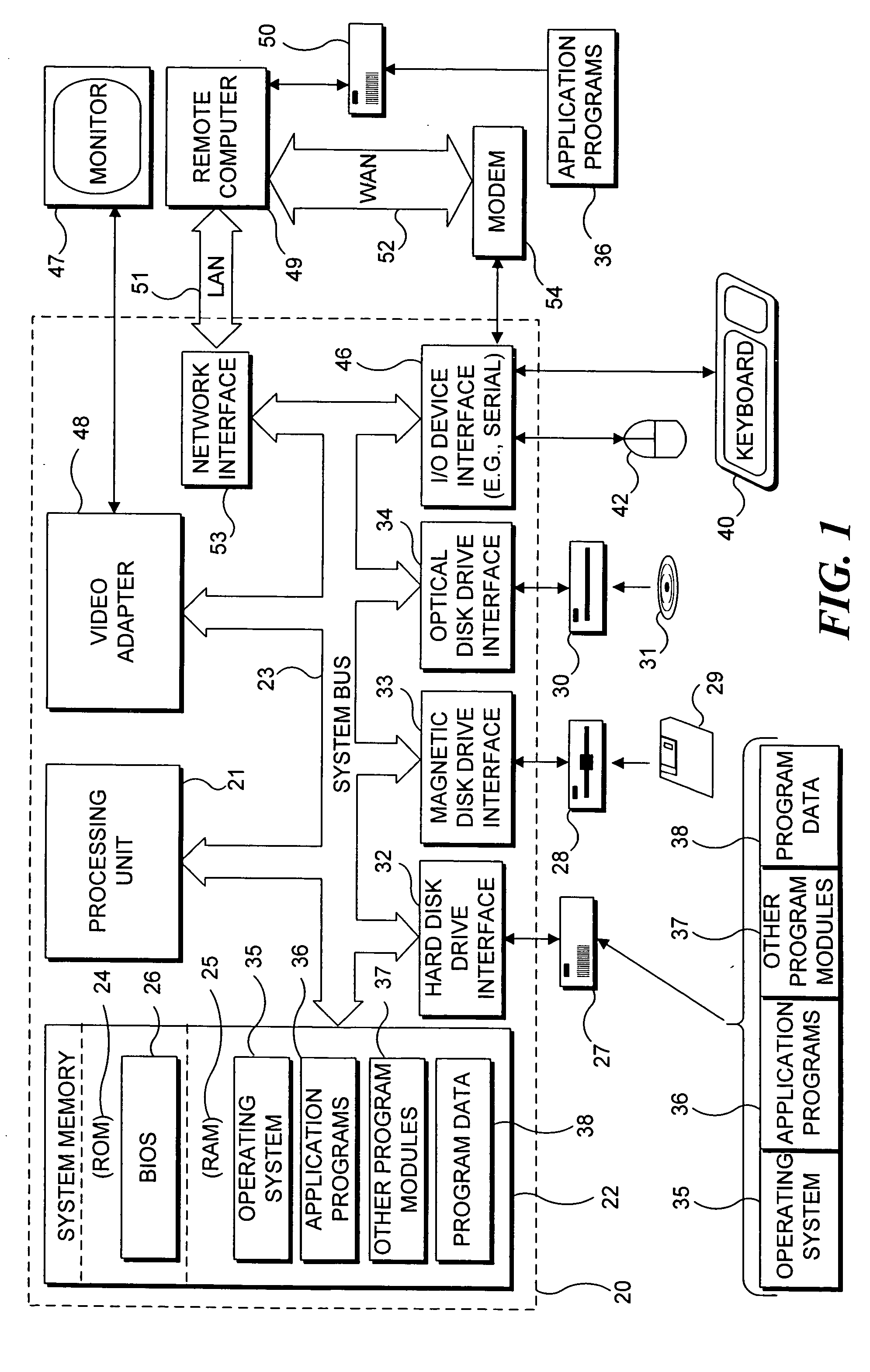
[0025] With reference to FIG. 1, an exemplary system suitable for implementing various portions of the present invention. The system includes a general purpose computing device in the form of a conventional PC 20, provided with a processing unit 21, a system memory 22, and a system bus 23. The system bus couples various system components including the system memory to processing unit 21 and may be any of several types of bus structures, including a memory bus or memory controller, a peripheral bus, and a local bus using any of a variety of bus architectures. The system memory includes read only memory (ROM) 24 and random access memory (RAM) 25. A basic input / output system 26 (BIOS), containing the basic routines that help to transfer information between elements within the PC 20, such as during start up, is stored in ROM 24. The PC 20 further includes a hard disk drive 27 for reading from and writing to a hard disk (not shown), a ...


PUM


Abstract

A display table contains a projector that can either project an image onto a display surface of the display table or onto an external surface that is separate from the display table. A user can change the path of the light from the projector from the display surface to the external surface, either by rotating the projector to an appropriate position, or by moving a mirror into the path of light from the projector. A video camera included in the display table also has dual functionality and can selectively be used either to image objects on or above the display surface, or objects that are not adjacent to the display surface. A panel in the housing of the table is opened, and either the video camera is pivoted or a mirror is moved into its light path. Imaging a user with the video camera is useful for video conferencing.

Description

FIELD OF THE INVENTION [0001] The present invention generally pertains to selectively modifying the projection path of a video image, and more specifically, pertains to a display system having the capability of enabling a user to selectively alter a light path for projecting a video image between a rear side of a display surface of the display system, and a separate surface that is not part of the display system. BACKGROUND OF THE INVENTION [0002] Many people enjoy viewing movies and other video images at their leisure, in the privacy of their homes, on television monitors or other types of display screens. The ready availability of recorded commercial movies as well as other video material on VHS tapes and more recently, on DVDs, has greatly increased the popularity of large screen televisions, and various types of monitors for viewing such video materials. In addition, a suitable video system can also be used for viewing digital photographs, over the air television programs, cable...

Claims


Application Information

Patent Timeline
IPC IPC(8): B60J7/22G03B21/14G03B21/28H04N5/74
CPCG03B21/28H04N7/142H04N5/74
Inventor DRUCKER, STEVEN M.WONG, CURTIS GLENN
Owner MICROSOFT TECH LICENSING LLC
Features
  • Generate Ideas
  • Intellectual Property
  • Life Sciences
  • Materials
  • Tech Scout
  • Unparalleled Data Quality
  • Higher Quality Content
  • 60% Fewer Hallucinations
Learn More