Switching dc power supply

a dc power supply and power supply technology, applied in the direction of electric variable regulation, process and machine control, instruments, etc., can solve the problems of power loss, switching loss too high for the power being consumed, and some problems left unresolved in the dual-mode driving of the voltage regulator switch, so as to achieve the effect of minimal interferen

Active Publication Date: 2005-11-10
SANKEN ELECTRIC CO LTD +1
View PDF4 Cites 36 Cited by
  • Summary
  • Abstract
  • Description
  • Claims
  • Application Information

AI Technical Summary

Benefits of technology

[0009] It is therefore an object of the instant invention to drive the voltage regulator switch at variable frequencies in both normal load and light load mode in or

Problems solved by technology

One of the problems encountered with the switching power supply outlined above is the power loss, known as switching loss, caused by the on-off operation of the voltage regulator switch.
Should the voltage regulator switch be driven under light load at a switching frequency that is the same as, or higher than, that under normal load, the resulting switching loss would be too high for the power being consumed.
Such dual-mode driving of the voltage regulator switch has had some problems left unresolved, however.
One of the problems arises from the fact that the switching fre

Method used


Image

  • Switching dc power supply
  • Switching dc power supply
  • Switching dc power supply

Examples


embodiment

OF FIG. 14

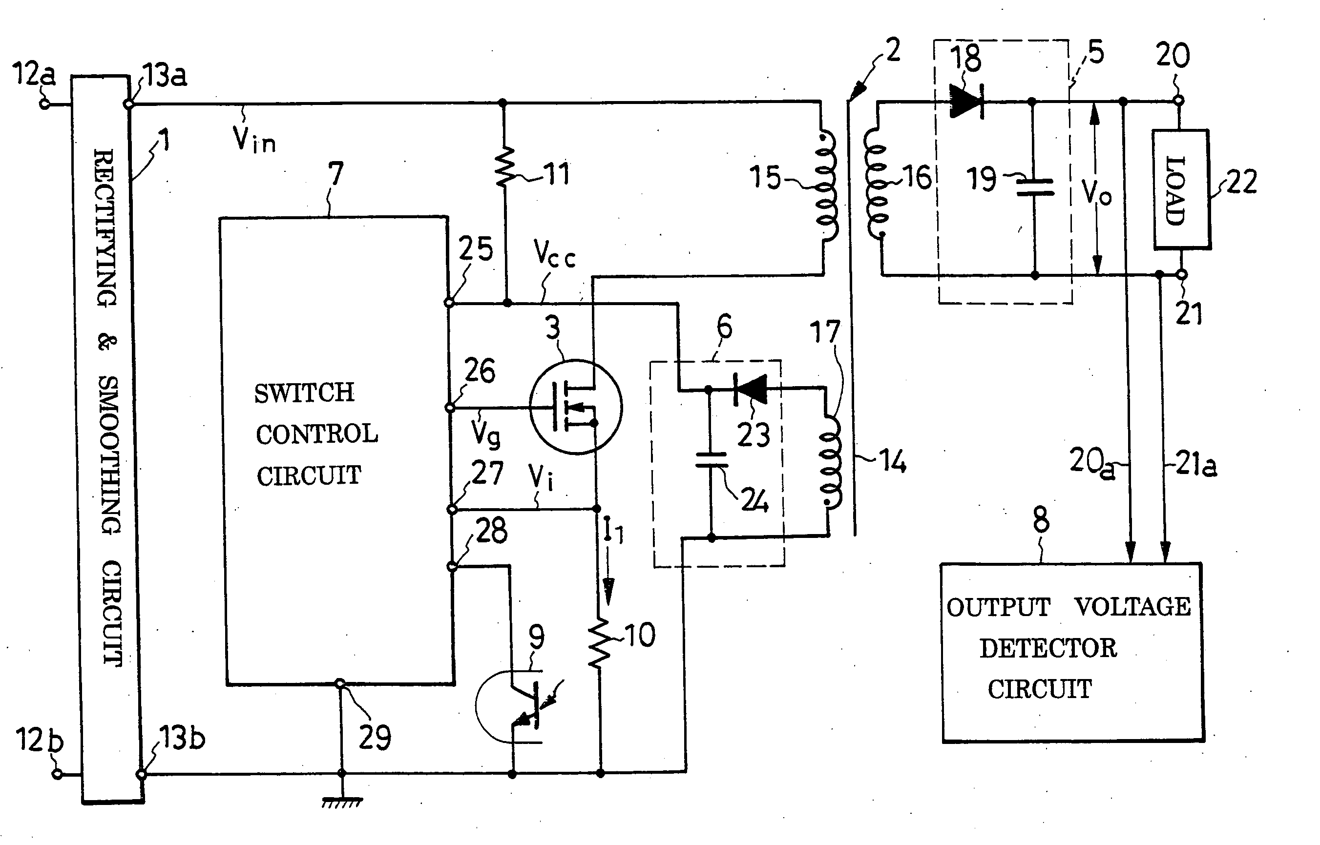
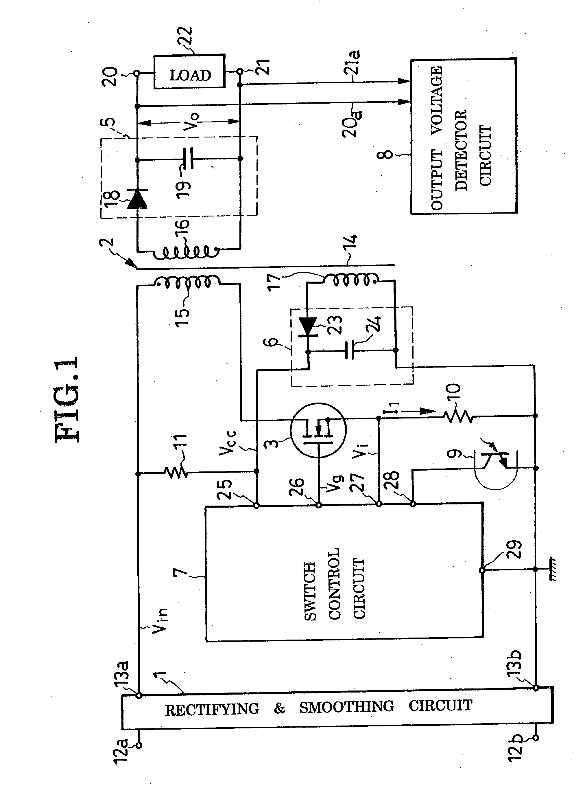
[0121] The switching power supply of FIG. 14 is similar in construction to that of FIG. 1 except that a reactor 2a is employed in place of the transformer 2 of the FIG. 1 embodiment, the reactor having no equivalent to the secondary winding 16 of the transformer. Another difference is that the output rectifying and smoothing circuit 5 is connected in parallel with the voltage regulator switch 3 and current detect resistor 10. All the other details of construction are as previously set forth with reference to FIGS. 1 to 3.

[0122] During the conducting periods of the voltage regulator switch 3, when the rectifying diode 18 of the output rectifying and smoothing circuit 5 is reverse biased, energy is stored on the reactor winding 15. The thus-stored energy is released to feed the load 22 during the nonconducting periods of the voltage regulator switch 3 when the rectifying diode 18 is forward biased. The capacitor 19 of the output rectifying and smoothing circuit 5 is charged...


PUM


Abstract

A transformer has a primary winding connected between a pair of dc input terminals via a voltage regulator switch, and a secondary winding connected between a pair of dc output terminals via a rectifying and smoothing circuit. The dc output voltage being applied to the load from the dc output terminals is detected, and the detector output voltage dually divided, to provide two feedback signals of different magnitudes. One of these feedback signals is used by a mode selector circuit to provide a mode select signal for causing the voltage regulator switch to be driven continuously under normal load, and at intervals under light load. Delivered to a conduction terminator circuit, the other feedback signal is thereby used to provide conduction terminator pulses for terminating conduction through the voltage regulator switch. A conduction initiator circuit responds both to the mode select signal and to a signal indicative of the conduction and nonconduction of the voltage regulator switch, to initiate conduction therethrough upon lapse of a preassigned length of time following the end of the previous conducting period. Although the nonconducting periods of the voltage regulator switch are thus fixed, its conducting periods are variable with the results of comparison of a switch current detect signal and the second recited feedback signal.

Description

CROSS REFERENCE TO RELATED APPLICATIONS [0001] This application claims priority to Japanese Patent Application No. 2004-070945, filed Mar. 12, 2004. BACKGROUND OF THE INVENTION [0002] This invention relates generally to switching dc power supplies, known also as dc-to-dc converters or switching regulator, and more particularly to such a power supply capable of providing a constant dc output voltage by negative feedback. Still more particularly, the invention pertains to a dual-mode switching power supply wherein the voltage regulator switch for holding the output voltage constant is driven (i.e. turned on and off) continuously under normal load and at intervals under light load, with a view to reduction of switching loss. [0003] The switching power supply of the type herein under consideration generally comprises a transformer having a primary winding connected to a pair of input terminals between which in turn are to be connected to a dc power supply, and a secondary winding connec...

Claims


Application Information

Patent Timeline
IPC IPC(8): H02M3/28H02M3/155H02M3/335
CPCH02M3/33523Y02B70/16H02M2001/0032H02M1/0032Y02B70/10H02M3/28
Inventor YAMADA, TOMOYASUFURUYA, MITSUGU
Owner SANKEN ELECTRIC CO LTD
Why Eureka
Try Eureka