Polishing pad, method of manufacturing glass substrate for use in data recording medium using the pad, and glass substrate for use in data recording medium obtained by using the method

a technology of data recording medium and polishing pad, which is applied in the direction of abrasive surface conditioning devices, instruments, lapping machines, etc., can solve the problems of frequent replacement of polishing pads, damage to the head, and damage to magnetic disks, so as to maintain the process yield of glass substrate, increase the manufacturing quantity of glass substrate, and improve the effect of quality

Active Publication Date: 2005-11-10
HOYA CORP
View PDF9 Cites 3 Cited by
  • Summary
  • Abstract
  • Description
  • Claims
  • Application Information

AI Technical Summary

Benefits of technology

[0007] The present invention was made by focusing attention on such problems as described above, involved in the prior art. The present invention has as its object the provision of a polishing pad which can promote increasing the manufacturing quantity of the glass substrate for use in data recording media while maintaining the process yield of the glass substrate with stable quality and a method of manufacturing the glass substrate for use in data recording media by using the polishing pad. The present invention also has as another object the provision of the glass substrate for use in data recording media, while maintaining the process yield with stable quality.

Problems solved by technology

When the head moves, if there are asperities on the surface of the magnetic disk, the head comes into contact with the asperities, so that there possibly occurs a problem in that the head is damaged and / or the magnetic disk scratched.
However, the Asker C hardness is the hardness obtained by measurement of the polishing pad, after the base and the polishing portion have been laminated together, but is not the hardness obtained by measurement only of the polishing portion that is actually for contact with the surface of a glass workpiece.
Thus, according to the polishing pad selected on the basis of the Asker C hardness, the time variation of the polishing portion leads to a fear of causing a problem including the possibility such that the quality of the manufactured glass substrate is not stabilized and the polishing pad must be frequently replaced.
Because of a fear of causing such a problem, there has been a problem such that it is difficult to increase the manufacturing quantity while maintaining the process yield of the glass substrate with stable quality.

Method used


Image

  • Polishing pad, method of manufacturing glass substrate for use in data recording medium using the pad, and glass substrate for use in data recording medium obtained by using the method
  • Polishing pad, method of manufacturing glass substrate for use in data recording medium using the pad, and glass substrate for use in data recording medium obtained by using the method

Examples


example 1

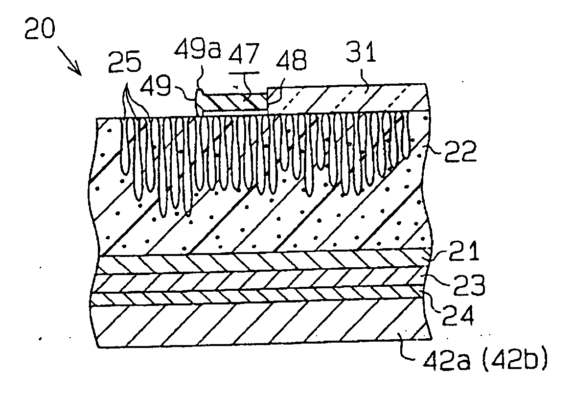
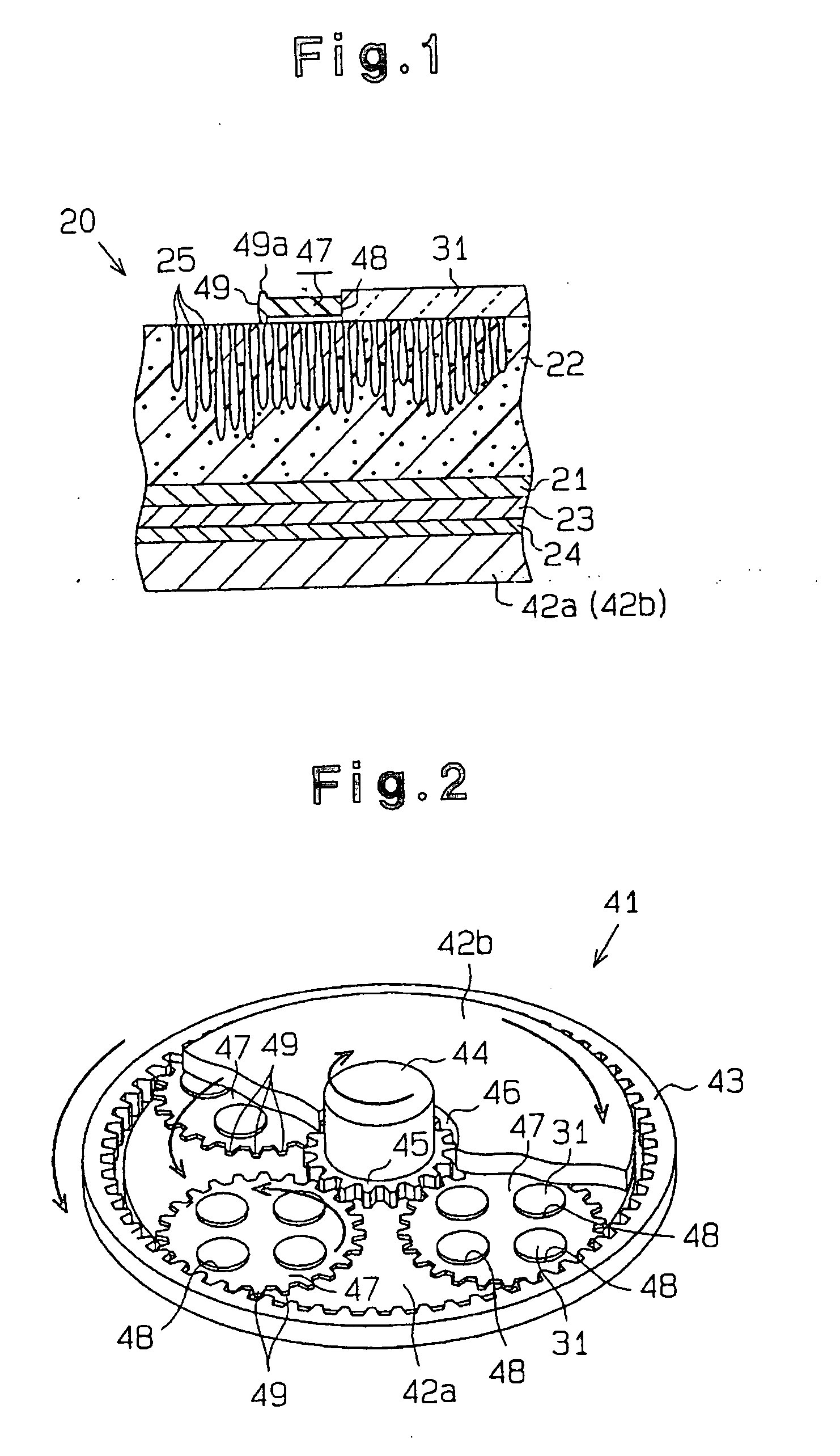
[0056] The polishing portion 22 was formed of a polyurethane having a 100% modulus of 8.83 MPa (90 kgf / cm2), and thus the soft pad 20 was prepared to obtain the polishing pad of Example 1. Then, the soft pad 20 was subjected to the dressing treatment in which the Ra and Rmax values of the surface of the polishing part 22 were respectively made to be 7 μm or less and 60 μm or less. The 100% modulus was derived as follows: the strength of a specimen made of the polyurethane was measured by use of an autograph when elongated by 100% at room temperature from its length prior to measurement and the 100% modulus was obtained by dividing the strength thus obtained by the sectional area existing at the time of the measurement. The Ra and Rmax values of the surface of the polishing portion 22 were measured by means of an SE3400 manufactured by Kosaka Laboratory Ltd. under setting conditions in which the stylus diameter was 20 μmf, the measurement length was 25 mm, the measurement speed was 0...

example 2

[0058] The polishing portion 22 was formed of a polyurethane having a 100% modulus of 11.8 MPa, and thus the soft pad 20 was prepared to obtain the polishing pad of Example 2. Then, a soft pad which had the same Ra and Rmax values as that in Example 1 was obtained without applying the dressing treatment. By using the soft pad 20, similarly to Example 1, the surfaces of plural sheets of glass workpieces 31 were polished to prepare glass substrates. In this case, the load exerted by the soft pad 20 on the glass workpieces 31 and the product of the load (gf / cm2) and the polishing period time (minutes) were set to be the same as those in Example 1. The obtained glass substrates had an average NRa value of 0.25 nm with an accompanying standard deviation of 0.05. The lifetime of the soft pad 20 was measured to be 125 hours.

example 3

[0059] The polishing portion 22 was formed of a polyurethane having a 100% modulus of 11.8 MPa, and thus the soft pad 20 was prepared to obtain the polishing pad of Example 3. Then, a soft pad which had the same Ra and Rmax values as that in Example 1 was obtained by applying the dressing treatment. By using the soft pad 20, similarly to Example 1, the surface of plural sheets of glass workpieces 31 was polished to prepare glass substrates. The obtained glass substrates gave the average NRa value of 0.20 nm with the accompanying standard deviation of 0.05. In this case, the product between the load exerted by the soft pad 20 to the glass workpieces 31 and the product between the load (gf / cm2) and the polishing period of time (minutes) were set to be the same as those in Example 1. The lifetime of the soft pad 20 was measured to be 125 hours.


PUM

PropertyMeasurementUnit
surface roughnessaaaaaaaaaa
Raaaaaaaaaaa
particle sizeaaaaaaaaaa

Abstract

A polishing pad used for precise polishing of the surface of a lapped glass workpiece when a glass substrate for use in data recording media is manufactured from a glass workpiece. The polishing pad comprises a base and a polishing portion laminated on the base and contacting the surface of the glass workpiece at the time of polishing. The polishing portion is formed of a foam made of a synthetic resin having a 100% modulus of 11.8 MPa or less. A type of parameter representing the surface roughness of the polishing portion, namely, the maximum height (Rmax), is 70 μm or less.

Description

BACKGROUND OF THE INVENTION [0001] The present invention relates to a polishing pad used in manufacturing magnetic disks for magnetic recording media in information recording devices such as hard disks, magneto-optic disks, and optical disks, a method of manufacturing glass substrates for use in data recording media by using the pad, and a glass substrate for use in data recording media obtained by the method. [0002] Conventionally, magnetic disks, which are one type of data recording media, are used in hard disk drive devices. Such magnetic disks are manufactured by laminating magnetic layers on the surface of glass substrates for use in data recording media (hereinafter referred to as glass substrates). In this connection, a magnetic head for reading information recorded on a magnetic disk (hereinafter sometimes referred to as a head) moves relative to the magnetic disk in a manner floating above and away from the surface of the magnetic disk. [0003] When the head moves, if there ...

Claims


Application Information

Patent Timeline
Patent Type & Authority Applications(United States)
IPC IPC(8): B24B1/00B24B37/005B24B37/20B24B37/22B24B37/26B24B53/017B24B53/02B24D13/14G11B5/73G11B5/84G11B7/24047G11B7/253G11B7/26G11B11/105
CPCB24B37/24B24B37/08
Inventor NAKANO, HIROMITAJIMA, HIROKAZU
Owner HOYA CORP
Why Eureka
Try Eureka