Controlled deflection roll

a deflection roll and control technology, applied in the direction of calenders, papermaking, textiles and paper, etc., can solve the problems of too complicated maintenance of such systems, and achieve the effect of increasing damping characteristics, fast pressure regulation, and regulating pressure changes so quickly

Inactive Publication Date: 2005-11-10
VOITH PATENT GMBH
View PDF29 Cites 6 Cited by
  • Summary
  • Abstract
  • Description
  • Claims
  • Application Information

AI Technical Summary

Benefits of technology

[0026] However, the throttling point can also be capable of control via an electric or magnetic field, and can in turn comprise an electric conductor, cable or the like for producing the field. Such a controlled variant has the advantage that the circulation volume flow of a respective source of support can be kept relatively constant irrespective of the pressure. In the case of the technically simpler variant mentioned previously, in which the throttling is carried out via capillaries or throttling points and in which the source of support is operated exclusively with the electrorheological fluid or ferrofluid, the circulating volume flow is approximately proportional to the piston pressure.
[0027] All the design variants permit very fast pressure regulation, since no connecting line is connected between the actuating element (a throttle which can be controlled electrically in the region of one millisecond by means of viscosity change) and the pressure chamber of the source of support. In the case of an oscillating roll shell, the pressure change can be regulated so quickly that it is possible to exert an active influence on the oscillation.
[0028] As already mentioned, the ERF or ferrofluid effect can also be used to specifically increase the damping characteristics of a respective source of support. For example, by connecting a voltage to the guide bush of a respective source of support, the viscosity of the fluid between the guide bush and the yoke can be highly increased locally, which leads to a considerable increase in the viscous damping of a source of support moved relative to the yoke. The guide bush in this case should be insulated electrically with respect to the head of the source of support, since otherwise, in the event of mixed friction of the head of the source of support on the rotating roll shell, it is possible for a voltage drop, or short circuit, to occur. These damping characteristics can likewise be influenced or regulated actively.

Problems solved by technology

Nevertheless, this design has been implemented only rarely in the past, which can be attributed to the fact that the maintenance of such systems appears to be too complicated and the technology appears to be too temperamental.

Method used


Image

  • Controlled deflection roll
  • Controlled deflection roll
  • Controlled deflection roll

Examples


Embodiment Construction

[0054] The particulars shown herein are by way of example and for purposes of illustrative discussion of the embodiments of the present invention only and are presented in the cause of providing what is believed to be the most useful and readily understood description of the principles and conceptual aspects of the present invention. In this regard, no attempt is made to show structural details of the present invention in more detail than is necessary for the fundamental understanding of the present invention, the description taken with the drawings making apparent to those skilled in the art how the several forms of the present invention may be embodied in practice.

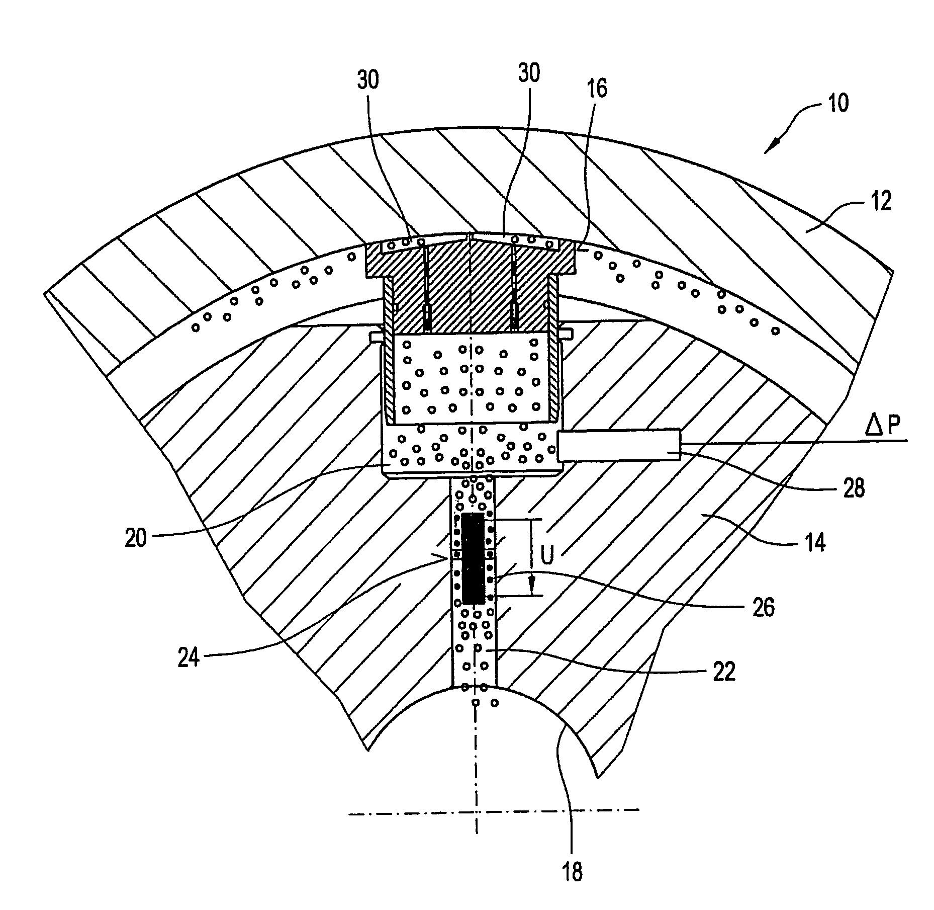
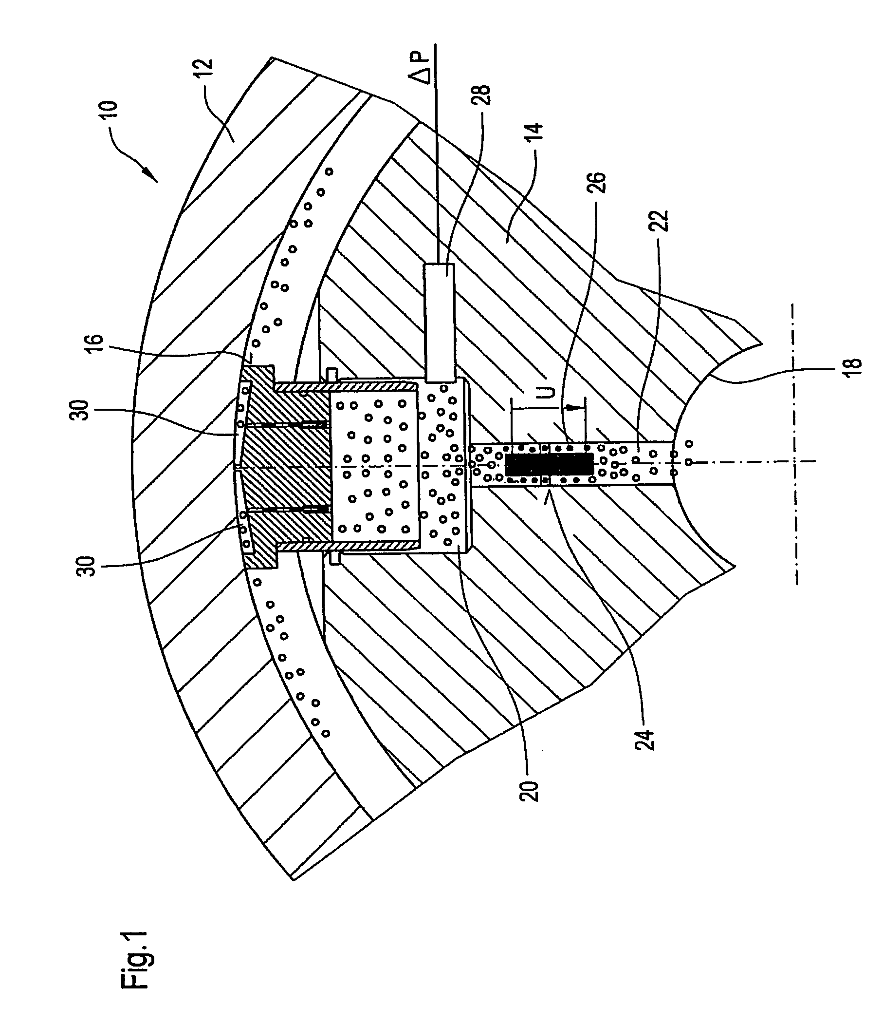
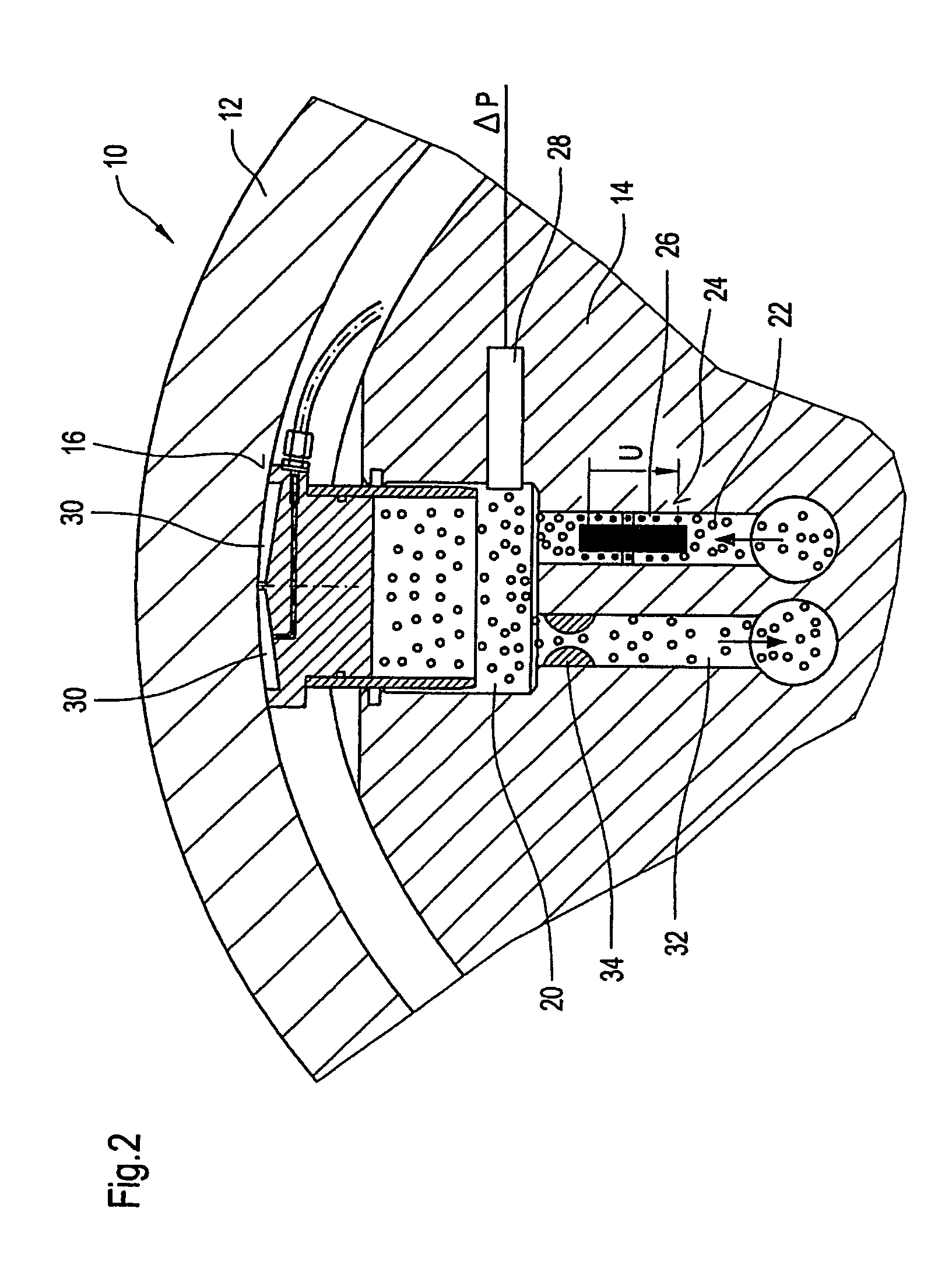
[0055]FIG. 1 shows schematically a controlled deflection roll 10, which comprises a revolving roll shell 12, a yoke 14 which passes axially through the roll shell 12 and is fixed against rotation, and at least one source of support 16 arranged between the yoke 14 and the roll shell 12.

[0056] The source of support 16 is...


PUM

PropertyMeasurementUnit
diameteraaaaaaaaaa
viscosityaaaaaaaaaa
electric fieldaaaaaaaaaa

Abstract

A controlled deflection roll has a revolving roll shell, a yoke which passes axially through the roll shell and is fixed against rotation, and at least one source of support arranged between the yoke and the roll shell. The source of support is at least partly operated with one of an electrorheological fluid (ERF) and a ferrofluid. The viscosity of the ERF and the ferrofluid can be varied using an electric field or a magnetic field.

Description

[0001] The present application claims priority under 35 U.S.C. § 119 of German Patent Application No. 10 2004 022 3777, filed on May 6, 2004, the disclosure of which is expressly incorporated by reference herin in their entireties. BACKGROUND OF THE INVENTION [0002] 1. Field of the Invention [0003] The invention relates to a controlled deflection roll having a revolving roll shell, a yoke which passes axially through the roll shell and is fixed against rotation, and at least one source of support arranged between the yoke and the roll shell. [0004] 2. Discussion of the Background Information [0005] The regulation of the pressure of controlled deflection rolls is carried out by means of hydraulic valves, of which a large number of circuit variants exist. These include, inter alia, the variants in which the relevant pressure regulating valves are integrated in the interior of the roll. In contrast with positioning outside the roll, a design of this type has special advantages in the e...

Claims


Application Information

Patent Timeline
Patent Type & Authority Applications(United States)
IPC IPC(8): D21G1/02F16C13/00
CPCF16C13/028
Inventor HAAG, ROLF VAN
Owner VOITH PATENT GMBH
Why Eureka
Try Eureka