
Automatic blood pressure measuring instrument and method thereof

a blood pressure measurement and automatic technology, applied in the field of blood pressure measuring instruments, can solve the problems of high cost, large trouble in measuring blood pressure, and inability to accurately measure blood pressure, and achieve the effect of easing the measurement of blood pressur

Inactive Publication Date: 2005-11-10
KIM YOU IN
View PDF10 Cites 30 Cited by
  • Summary
  • Abstract
  • Description
  • Claims
  • Application Information

AI Technical Summary

Benefits of technology

[0008] It is, therefore, an object of the present invention to provide an automatic blood pressure measuring instrument and method, capable of measuring a blood pressure even though infants, low blood pressure patients, intensive care patients, etc. can not be measured by an existing blood pressure measuring instrument, and capable of expanding an application range as a vascular automatic diagnosis device using a pulse wave, including simply blood pressure measurement.
[0009] Further, it is another object of the present invention to provide an automatic blood pressure measuring instrument and method, capable not only of continuously measuring systolic and diastolic blood pressures for a short and long time, but also of monitoring for a long time by a non-invasive method.
[0013] Moreover, the first notch filter comprises an OP amplifier for amplifying the signals amplified at the pulse wave signal amplifying means and inputted a non-inverting terminal thereof, a low-pass filter provide on a loop fed from an output terminal of the OP amplifier back to an inverting terminal and for removing the noise of the commercial frequency, a first variable resistor connected in parallel with the non-inverting terminal of the OP amplifier, and a second variable resistor connected in parallel with the low-pass filter, whereby the first notch filter adjusts the cut-off frequency of the applied signals.
[0015] Meanwhile, the filtering section comprises a fourth low-pass filter for removing a noise from the amplified signals applied from the amplifying section, a third impedance matching means for matching an impedance of the input signal applied from the fourth low-pass filter and an impedance of an output signal, and a second notch filter for removing the noise of the commercial frequency of the signals applied from the third impedance matching means.
[0021] In other words, the present invention is characterized in that anyone not a medical expert can measure the blood pressure with ease by sensing the pulse wave at a pressure sensor, sensing and comparing and analyzing systolic and diastolic pressures, measuring maximum and minimum pressures through a series of operation processes, and displaying the measured results on the display.

Problems solved by technology

However, it requires much trouble and heavy cost in measuring the blood pressure, and has various disadvantages, such as circulatory problem of the blood, infection, blood clot and so on, in the course of inserting the catheter into the artery.
For these reasons, the invasive method has been used in an extremely limited range.
However, the non-invasive method is not only very inaccurate, but also is responsible for a tissular trauma.
Further, it is impossible to apply to infants or low blood pressure patients, and above all to perform continuous monitoring.
However, in the case of using only the pulse wave velocity or the pulse arrival time, it is impossible to ensure accomplishment of reliable blood pressure monitoring

Method used


Image

  • Automatic blood pressure measuring instrument and method thereof
  • Automatic blood pressure measuring instrument and method thereof
  • Automatic blood pressure measuring instrument and method thereof

Examples


Embodiment Construction

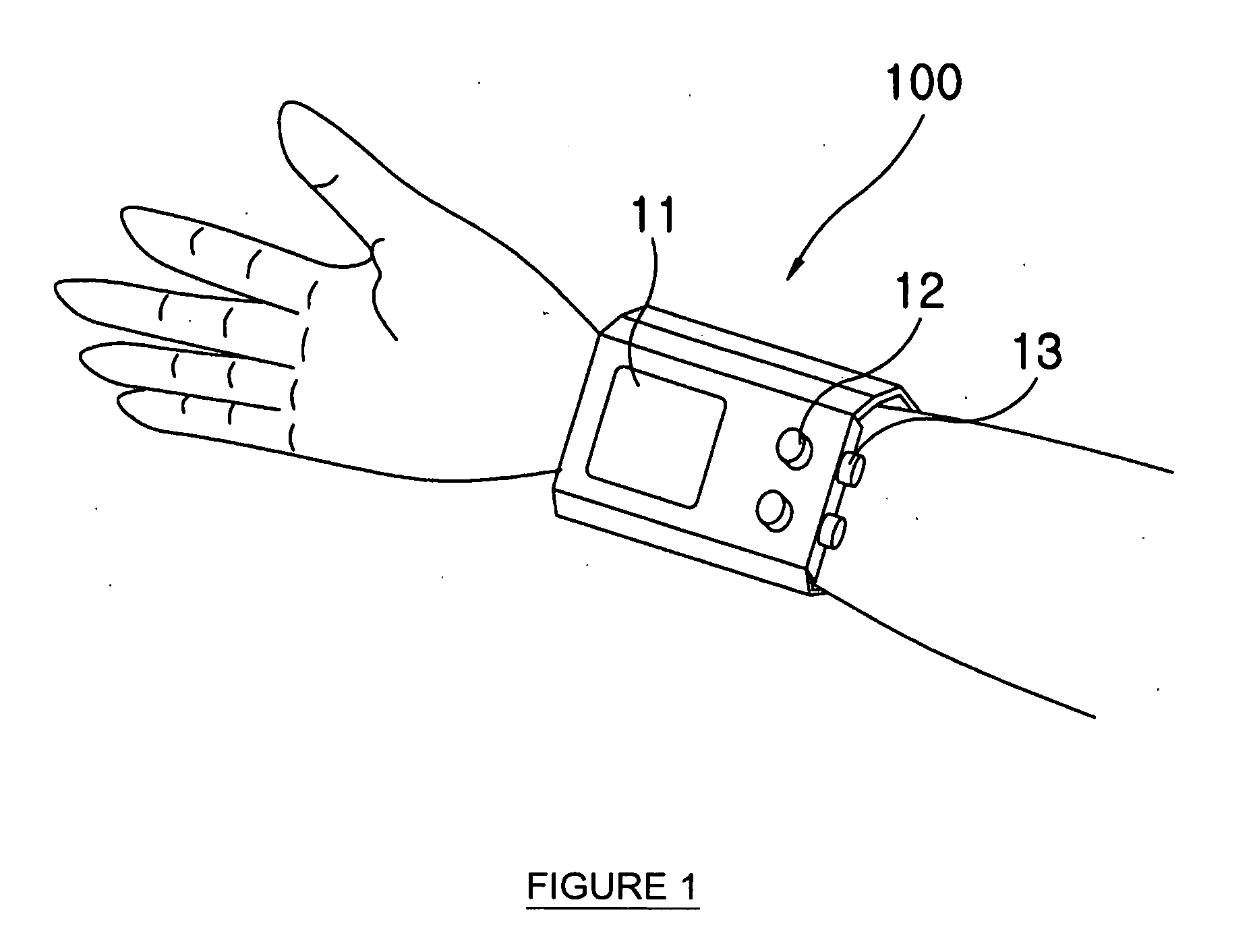
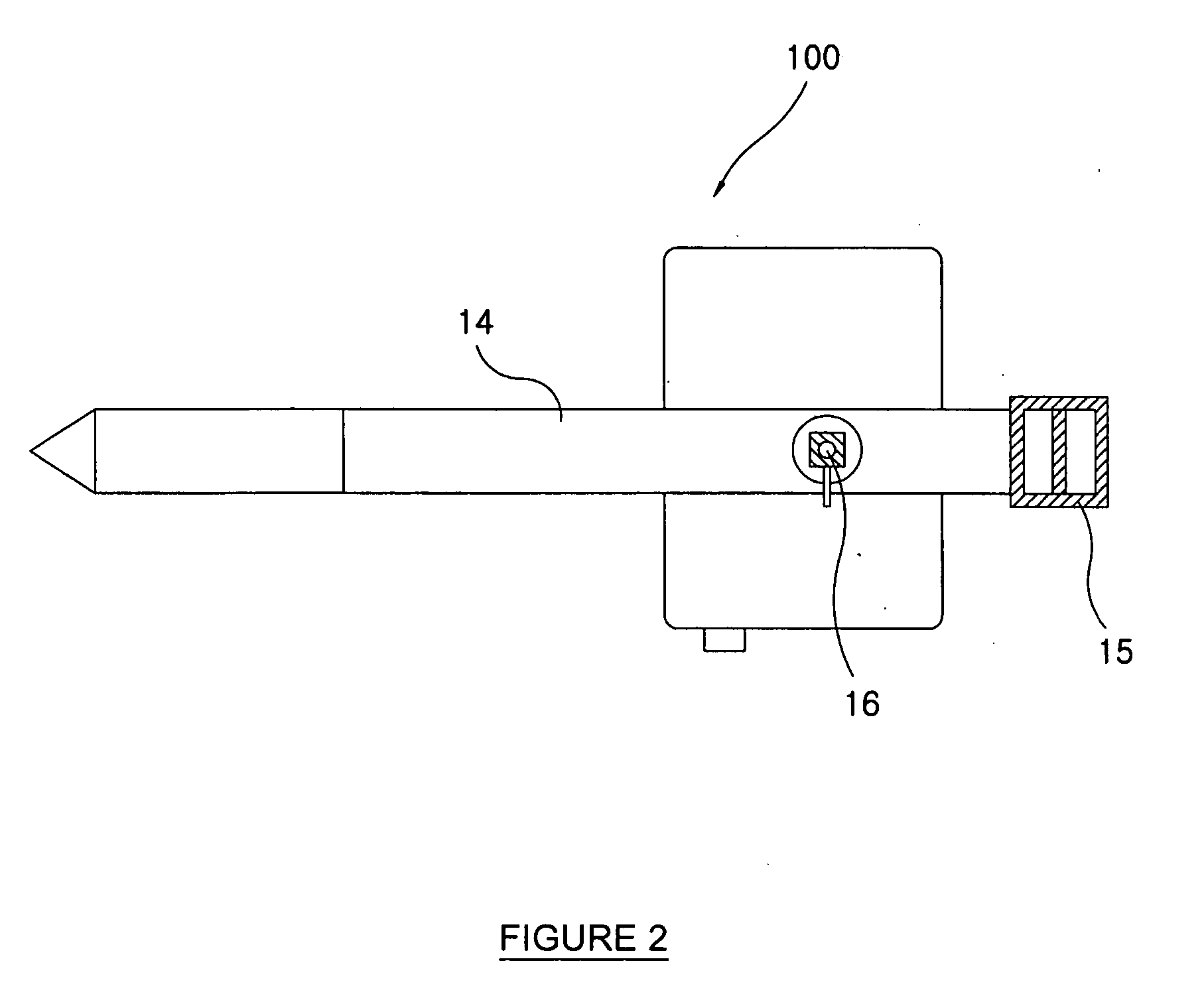
[0038] A preferred embodiment of the present invention will now be described with reference to the accompanying drawings.

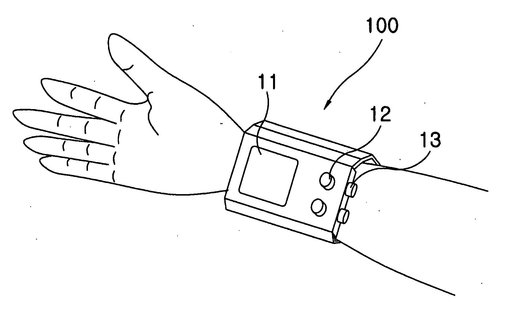
[0039]FIG. 1 is a perspective view showing an automatic blood pressure measuring instrument according to a preferred embodiment of the present invention. FIG. 2 is a bottom view of FIG. 1. FIG. 3 is a side view of FIG. 1.

[0040] A reference numeral 100 indicates an automatic blood pressure measuring instrument, 11 indicates a display, 12 indicates manipulating keys, 13 indicates electrocardiogram (ECG) connection ports, 14 indicates a band, 15 indicates a buckle, 16 indicates a pressure sensor, and 17 indicates an ECG monitor.

[0041] The display 11 is for displaying a measured blood pressure. The manipulating keys 12 are for inputting a manipulation signal of a user. The ECG connection ports 13 are for connecting with the ECG monitor 17. The ECG monitor 17 measures a systolic blood pressure and a diastolic blood pressure. The band supports the automatic blood pre...


PUM


Abstract

Disclosed is an automatic blood pressure measuring instrument and method designed to obtain a pulse wave signal and electrocardiogram (ECG) signals from a pressure sensor and an ECG monitor, to analyze correlation between both signals, to operate a maximum blood pressure and a minimum blood pressure based on the analyzed data, and to output the operated result to a display. The automatic blood pressure measuring instrument comprises a pressure sensor for obtaining a pulse wave from a wrist of the subject, a pulse wave signal processing section for amplifying, filtering and noise-removing the pulse wave applied from the pressure sensor, an electrocardiogram monitor for measuring a systolic blood pressure and a diastolic blood pressure and converting the measured results into electrical signals, an electrocardiogram signal processing section for amplifying, filtering and noise-removing the converted electrocardiogram measurement signals applied from the electrocardiogram monitor, an A / D converting section for converting the AC signals, which are applied from both the pulse wave signal processing section and the electrocardiogram signal processing section, into DC signals, a controlling section for comparing and analyzing the pulse wave signal and the electrocardiogram signals applied through the A / D converting section to operate the blood pressure of the subject, and a display for displaying the blood pressure of the subject operated at the controlling section.

Description

TECHNICAL FIELD [0001] The present invention relates to a blood pressure measuring instrument, and more particularly to an automatic blood pressure measuring instrument and method designed to obtain a pulse wave signal and electrocardiogram (ECG) signals from a pressure sensor and an ECG monitor, to analyze correlation between both signals, to operate a maximum blood pressure and a minimum blood pressure based on the analyzed data, and to output the operated result to a display. BACKGROUND ART [0002] As the number of the home health aged has been increased due to the general aging of society, a gradually increasing attention has been drawn to welfare and care for the aged. Thus, the approach of an elderly health care has begun to occur in a new scheme at various angles, and a concentrated attention has been paid to a blood pressure measurement functioning as the basis of health check-up. [0003] Measurement of a blood pressure, as one of current generalized clinical tests, is carried...

Claims


Application Information

Patent Timeline
Patent Type & Authority Applications(United States)
IPC IPC(8): A61B5/022A61BA61B5/02A61B5/0245A61B5/308
CPCA61B5/022A61B5/681A61B5/0428A61B5/0402A61B5/318A61B5/30A61B5/02A61B5/308A61B5/33
Inventor KIM, YOU-IN
Owner KIM YOU IN
Learn More