
Decoding an alternator output signal

a technology of output signal and alternator, applied in the direction of transmission monitoring, rapid change measurement, instruments, etc., can solve the problems of poor cylinder contribution, instrument display, and complicated or time-consuming connection to the engine, and achieve the effect of enhancing the dynamic range of signal processing

Inactive Publication Date: 2005-11-10
SNAP ON INC
View PDF27 Cites 15 Cited by
  • Summary
  • Abstract
  • Description
  • Claims
  • Application Information

AI Technical Summary

Benefits of technology

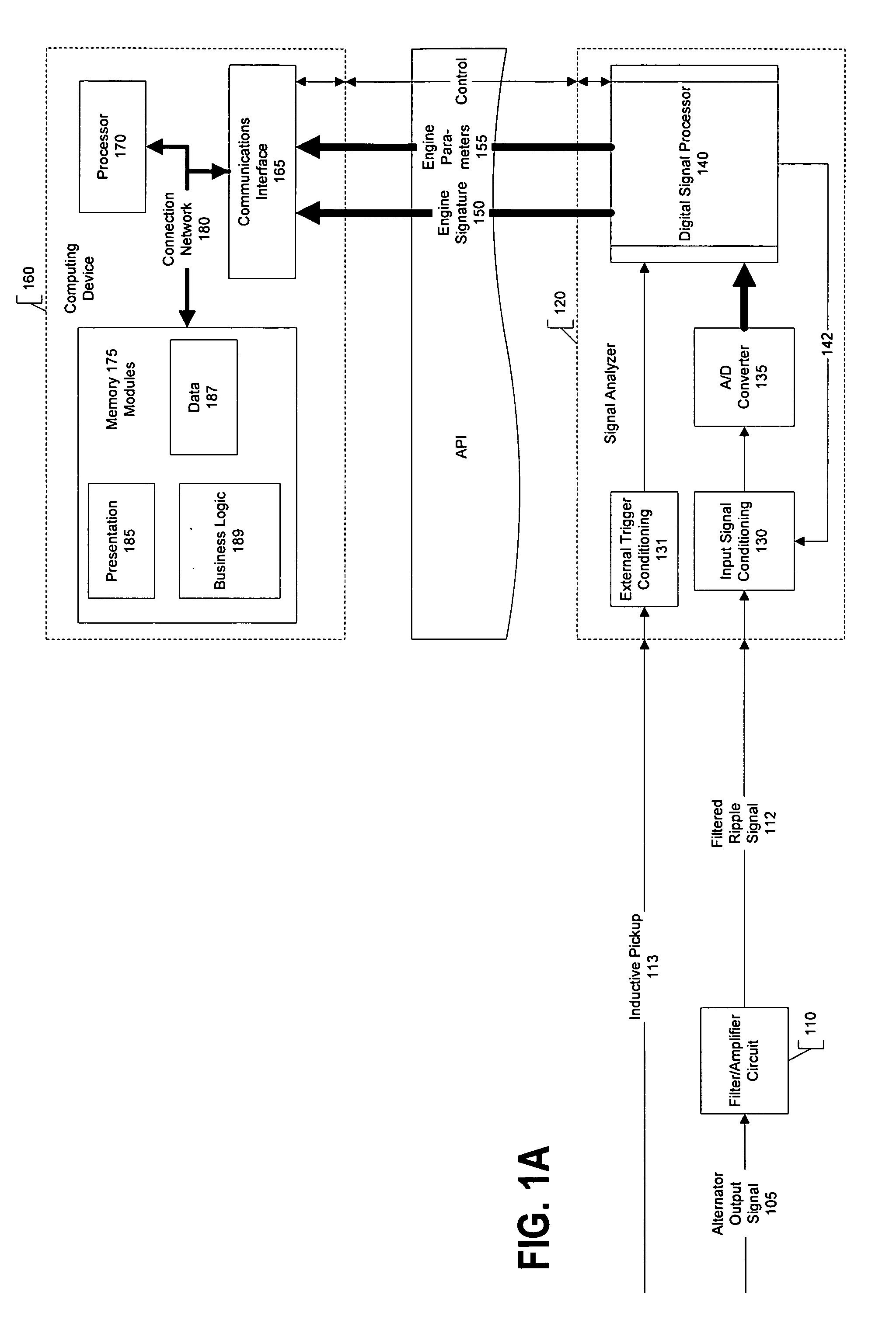
The present patent describes an engine diagnostic system that allows a service technician to evaluate engine cylinder contribution to output power. The system includes a filter / amplifier circuit that removes unwanted electric interference to produce a filtered ripple signal. The signal processing system decodes the filtered ripple signal into indexed engine data that reflects the engine speed independent of the revolutions per minute (RPM). The system also includes an angle demodulator that demodulates the diode ripple signal to produce the indexed engine data. The technical effect of the patent is to provide a reliable and accurate tool for evaluating engine performance.

Problems solved by technology

One type of engine performance problem found in internal combustion engines is poor cylinder contribution.
One problem with conventional diagnostic instruments that measure cylinder contribution is that they often require complicated or time-consuming connections to the engine.
Further, conventional diagnostic instruments may display results that are difficult to interpret or provide only general information.
That is, a technician may invest time setting up a diagnostic instrument yet not receive specific enough information about a problem or performance issue to perform a repair efficiently.
One problem with these approaches, however, is the accuracy or precision of the resulting demodulated signal.
The diode ripple signal is typically corrupted by electrical noise or other signals that emanate from various sources.
For example, the alternator itself may produce undesirable transients and amplitude modulations in the diode ripple signal.
These noise signals can make it difficult to demodulate the diode ripple signal accurately or precisely.
Given that an engine performance problem is likely attributable to the malfunction of a single engine cylinder, a technician does not want to receive inaccurate information and, therefore, consume diagnostic or repair time on a properly functioning cylinder.

Method used


Image

  • Decoding an alternator output signal
  • Decoding an alternator output signal
  • Decoding an alternator output signal

Examples


Embodiment Construction

[0036] The present disclosure is now described more fully with reference to the accompanying figures, in which several embodiments are shown. The embodiments described herein may include or be utilized with any appropriate engine having an appropriate voltage source, such as a battery, an alternator and the like, providing any appropriate voltage, such as about 6 Volts, 12 Volts, 24 Volts, 42 Volts and the like. As one skilled in the art will appreciate from the following detailed description, the embodiments described herein may operate independent of a particular direct current (DC) voltage. The embodiments described herein may be used with any desired system or engine. Those systems or engines may comprise items utilizing fossil fuels, such as gasoline, diesel, natural gas, propane and the like, electricity, such as that generated by battery, magneto, solar cell and the like, wind and hybrids or combinations thereof. Those systems or engines may be incorporated into other systems...


PUM

PropertyMeasurementUnit
cutoff frequencyaaaaaaaaaa
frequencyaaaaaaaaaa
voltageaaaaaaaaaa

Abstract

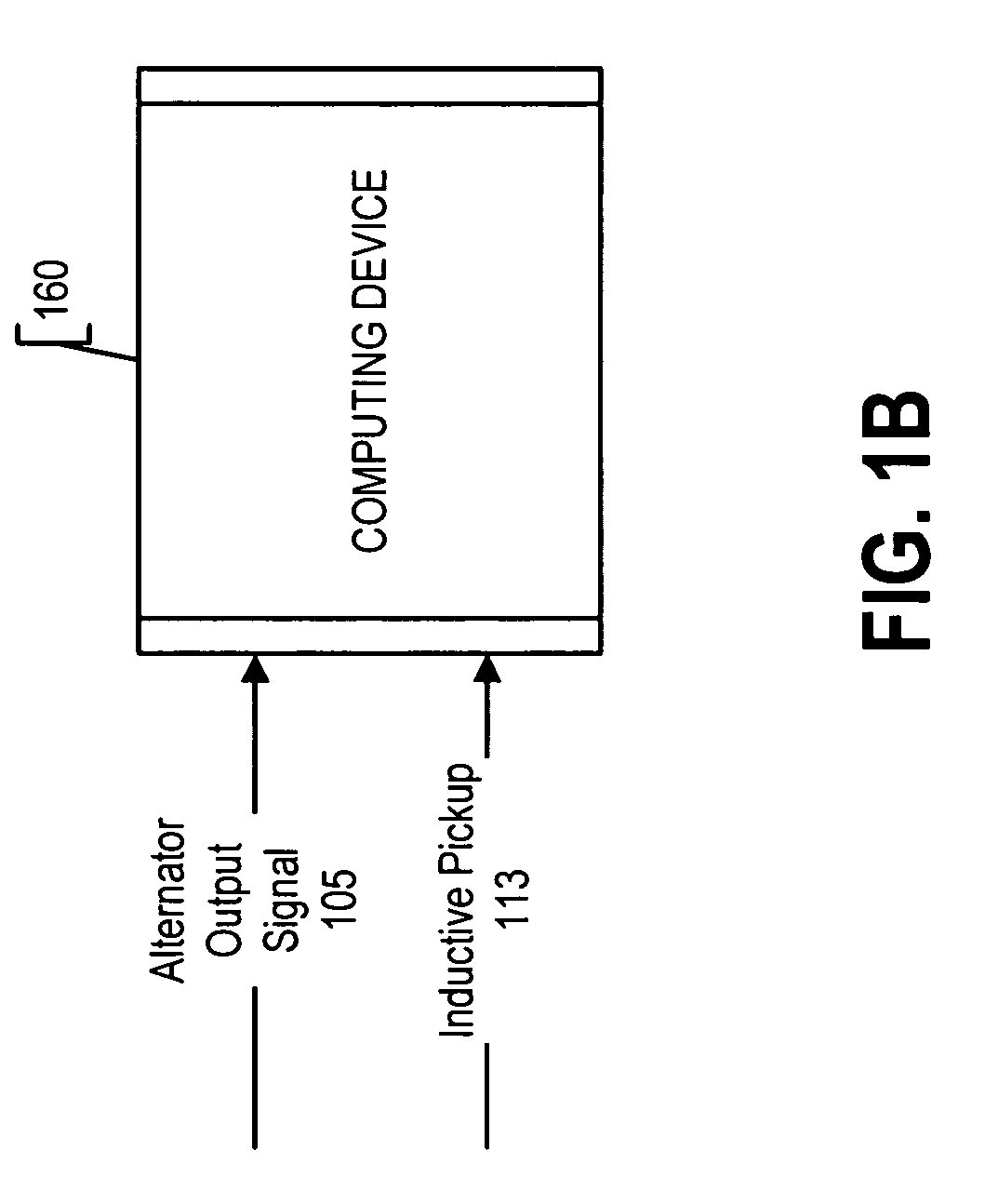
An engine diagnostic system is provided that enables a service technician to evaluate engine cylinder contribution to output power. The service technician couples one or more signal leads to the vehicle's battery, alternator, or accessory receptacle (e.g., cigarette lighter receptacle) to provide an alternator output signal to a signal analyzer. The signal analyzer processes the alternator output signal to generate an engine signature, which represents engine cylinder contribution to engine output power.

Description

RELATED APPLICATION [0001] This application is related to the U.S. Patent Application of DeCarlo et al., entitled “Determining Engine Cylinder Contribution from Indexed Engine Data,” filed on even date herewith.TECHNICAL FIELD [0002] The present disclosure relates generally to engine diagnostics, and more particularly, to evaluating engine cylinder contribution to output power by analyzing the diode ripple signal from an alternator driven by the engine. BACKGROUND [0003] One type of engine performance problem found in internal combustion engines is poor cylinder contribution. In a properly functioning engine, each cylinder contributes equally to the total output power for balanced operation. One problem with conventional diagnostic instruments that measure cylinder contribution is that they often require complicated or time-consuming connections to the engine. Further, conventional diagnostic instruments may display results that are difficult to interpret or provide only general inf...

Claims


Application Information

Patent Timeline
Patent Type & Authority Applications(United States)
IPC IPC(8): G01L23/08G06F17/00
CPCG01L23/085
Inventor DECARLO, ROBERT D.MUTZABAUGH, DENNIS M.STOFFELS, NICOLAAS M. J.
Owner SNAP ON INC
Learn More