Door handle system

Active Publication Date: 2005-11-17
NIFCO INC
View PDF12 Cites 15 Cited by
  • Summary
  • Abstract
  • Description
  • Claims
  • Application Information

AI Technical Summary

Benefits of technology

[0010] According to a third aspect of the present invention, the damper is provided with a channel sectional area changing device for reducing a channel sectional area for oil enclosed in a cylinder as a piston speed increases.
[0012] In the first aspect of the present invention, the damper does not need to directly connect the door opening lever. Accordingly, it is possible to construct the system so as not to apply a resistance of the damper to the door opening lever during the opening operation without a gear or clutch mechanism. Accordingly, it is possible to simplify the construction of the door handle system having the damper and effectively reduce manufacturing cost. In the second aspect, it is possible to arbitrary and widely set a relationship between a rotational angle of the door opening lever and a damping force applied to the piston rod through a setting of a cam profile. In the third aspect, it is possible to apply an optimal damping force according to an angular speed of the door opening lever from the closed position where the spring resilience becomes a maximum value to the initial position where the spring resilience becomes a minimum value. In the fourth aspect, it is possible to reduce the resistance applied to the piston when the damper extends. Accordingly, it is possible to smoothly follow the movement of the door opening lever during the opening operation while the damper is set to obtain a sufficient damping force when contracted.

Problems solved by technology

The one-way damper disclosed in Patent Reference 1, however, tends to have a complex structure, as it requires, among other elements, gear and clutch mechanisms.
For this reason, any attempt to construct the door handle system so that the door opening lever does not make an impulsive sound when it returns to the initial position inevitably increases manufacturing cost.

Method used


Image

  • Door handle system
  • Door handle system
  • Door handle system

Examples


Embodiment Construction

[0020] Hereunder, embodiments of the present invention will be explained in detail with reference to the attached drawings.

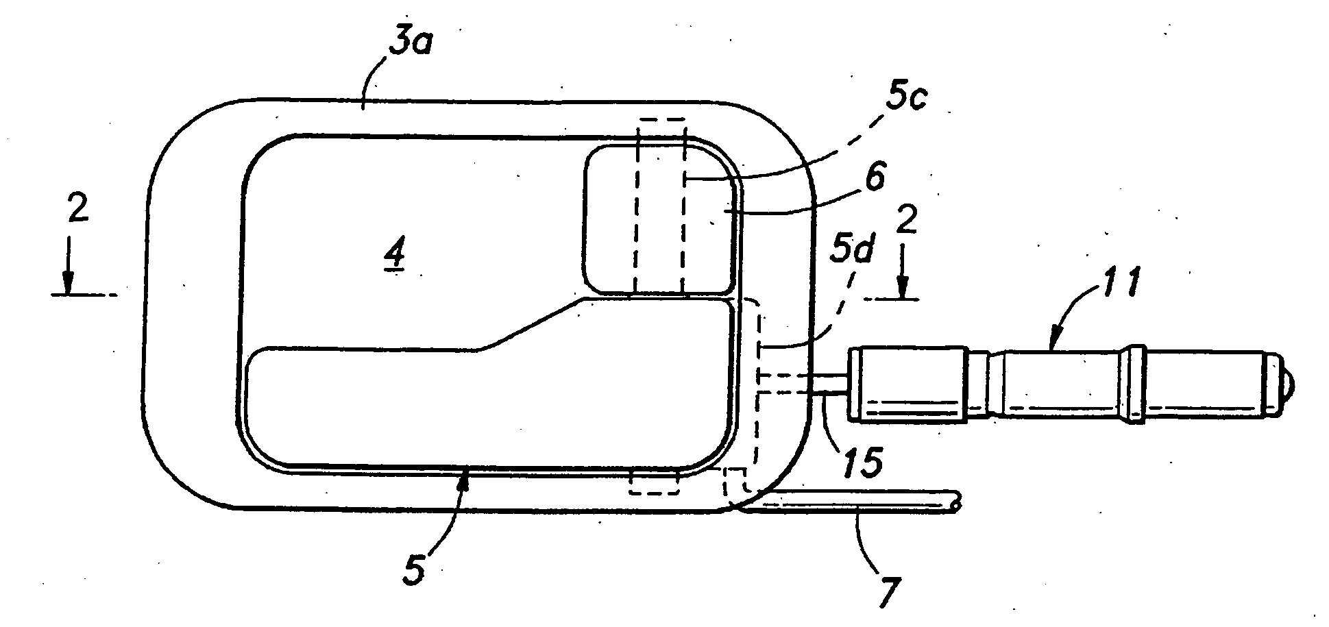
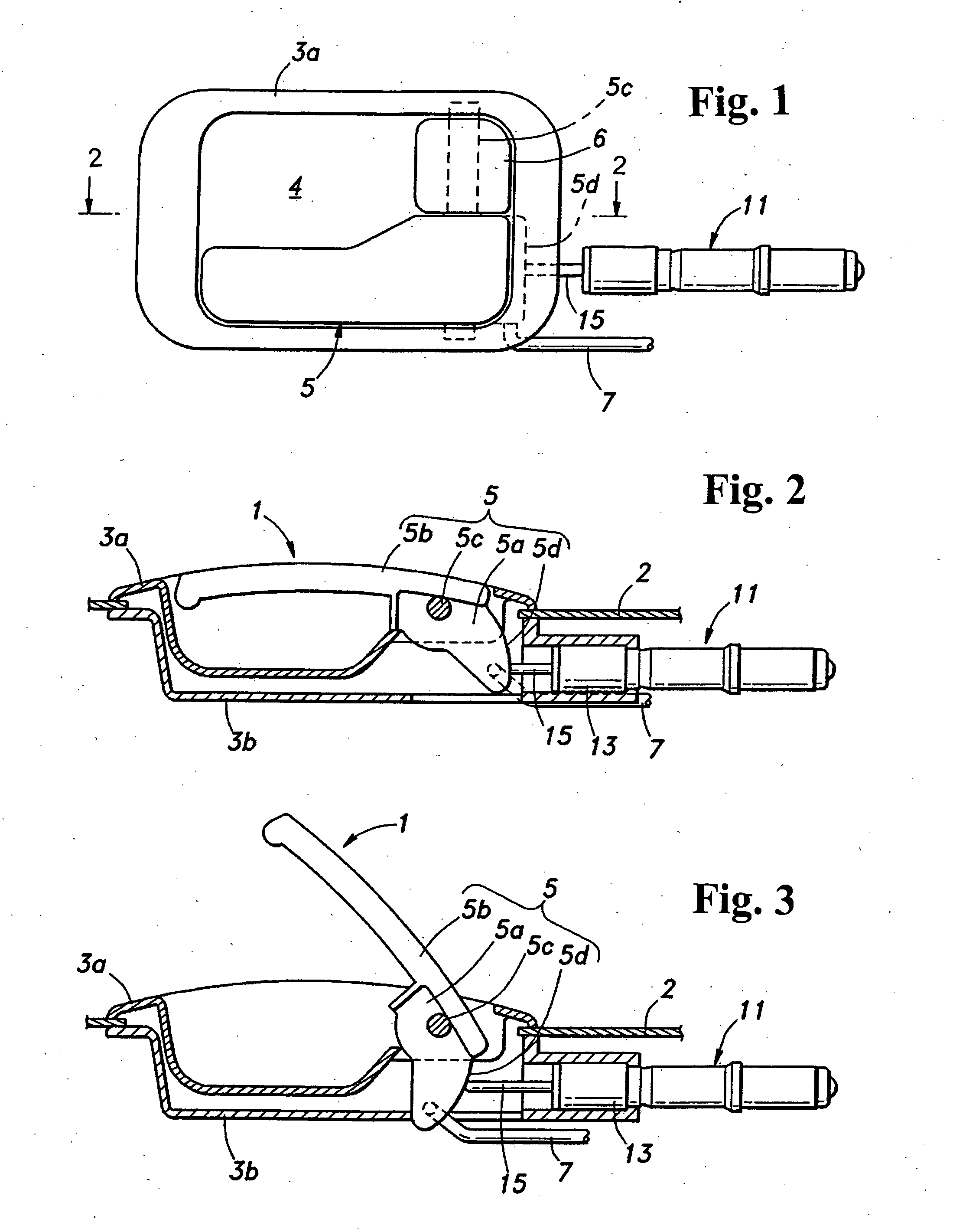
[0021]FIGS. 1 and 2 show an automotive inside door handle system to which the present invention is applied. An inside door handle system 1 has an outer frame 3a and an inner frame 3b to be integrated with an inner panel 2 of a door; and a door opening lever 5 and a locking lever 6 installed to be received within a recess 4 formed in a cabin side surface of the outer frame 3a.

[0022] The door opening lever 5 integrally comprises a body 5a, which is the center of the angular movement, a lever 5b, which extends from the body 5a in the direction perpendicular to the rotational axis, a shaft 5c, which coaxially projects vertically from the body 5a, and a cam 5d, which is disposed on the opposite side of the lever 5b across the shaft 5c. The locking lever 6 is pivoted to an upper side of the shaft 5c, and upper and lower ends of the shaft 5c are respectively pivoted ...


PUM


Abstract

A door handle system includes a door opening lever rotationally supported on a support member, and a damper having a linear piston sliding mechanism. The door opening lever has an angle change device for changing an angle when the door opening lever is actuated. The damper is attached to the support member and arranged to contact the angle change device so that a returning force of the door opening lever after being opened is reduced by the damper.

Description

BACKGROUND OF THE INVENTION AND RELATED ART STATEMENT [0001] The present invention relates to a door handle system of an automobile, in particular a door handle system having a damper for controlling a speed of a door opening lever returning to an initial position. [0002] An automotive door is provided with a door handle system to operate the door. The door handle system includes a door opening lever interlocked with a latch mechanism for holding the door shut and resiliently biased by a torsion coil spring or the like toward a returning direction. When the door opening lever is pulled against the resilient bias force, the latch mechanism connected to the door opening lever is released to open the door. When the hand is removed from the door opening lever, the door opening lever automatically returns to an initial position with the resilient bias force. [0003] A conventional door handle system occasionally makes an impulsive sound when the door opening lever briskly returns to the i...

Claims


Application Information

Patent Timeline
IPC IPC(8): E05B1/00B60J5/04E05B5/02E05B17/00E05B77/42E05B85/12E05F3/10F16F9/10F16F9/14F16F9/16F16F9/22
CPCE05B85/12E05B85/13Y10S292/23Y10T16/304Y10T16/458Y10T16/44E05B77/42Y10T292/57F16F9/103F16F9/14F16F9/16F16F9/22B60J5/04E05B1/00
Inventor NISHIYAMA, MASAYUKITOMIJI, KATSUYASU
Owner NIFCO INC
Why Eureka
Try Eureka