Exhaust gas cleaning device for internal combustion engine

a technology for cleaning devices and internal combustion engines, applied in electrical control, speed sensing governors, separation processes, etc., can solve the problems of fuel consumption, energy loss, fuel consumption needs to be concerned, etc., and achieve the effect of regenerating a particulate filter and low fuel consumption

Active Publication Date: 2005-11-17
DENSO CORP
View PDF9 Cites 53 Cited by
  • Summary
  • Abstract
  • Description
  • Claims
  • Application Information

AI Technical Summary

Benefits of technology

[0011] The present invention addresses the above disadvantage. Thus, it is an objective of the present invention to provide an exhaust gas cleaning device of an internal combustion engine, which can effectively regenerate a particulate filter while achieving relatively low fuel consumption.

Problems solved by technology

In each of the above cases, the energy, which is not converted into the engine power, is wasted, so that the fuel consumption needs to be concerned.
However, when the temperature of the DPF is rapidly increased, the DPF may be damaged.
However, with respect to the above two methods for increasing the temperature of the DPF, the one method, which increases the temperature of the exhaust gas and supplies the exhaust gas to the DPF, results in the loss of energy, which is lost through the engine or the exhaust pipe.
However, in the single DPF system, when the method of increasing the uncombusted HC is used, the following disadvantageous point exists.
However, when the temperature of the DPF is below a predetermined temperature, the catalyst is not activated effectively, so that the HC cannot be sufficiently combusted.
When the large amount of uncombusted HC is exhausted from the engine at the low temperature of the exhaust gas, the unreacted HC may adhere to the catalyst to cause poisoning of the catalyst.
Thus, the collected PM, which is collected at the upstream end of the DPF, cannot be sufficiently combusted and cannot be sufficiently removed.
As a result, the upstream end of the DPF may be clogged by the PM.
However, the method for increasing the exhaust gas temperature by, for example, throttling the intake air, is limited to a range, which does not cause misfiring.
Thus, the temperature increase is limited to the unsatisfactory level.

Method used


Image

  • Exhaust gas cleaning device for internal combustion engine
  • Exhaust gas cleaning device for internal combustion engine
  • Exhaust gas cleaning device for internal combustion engine

Examples


Embodiment Construction

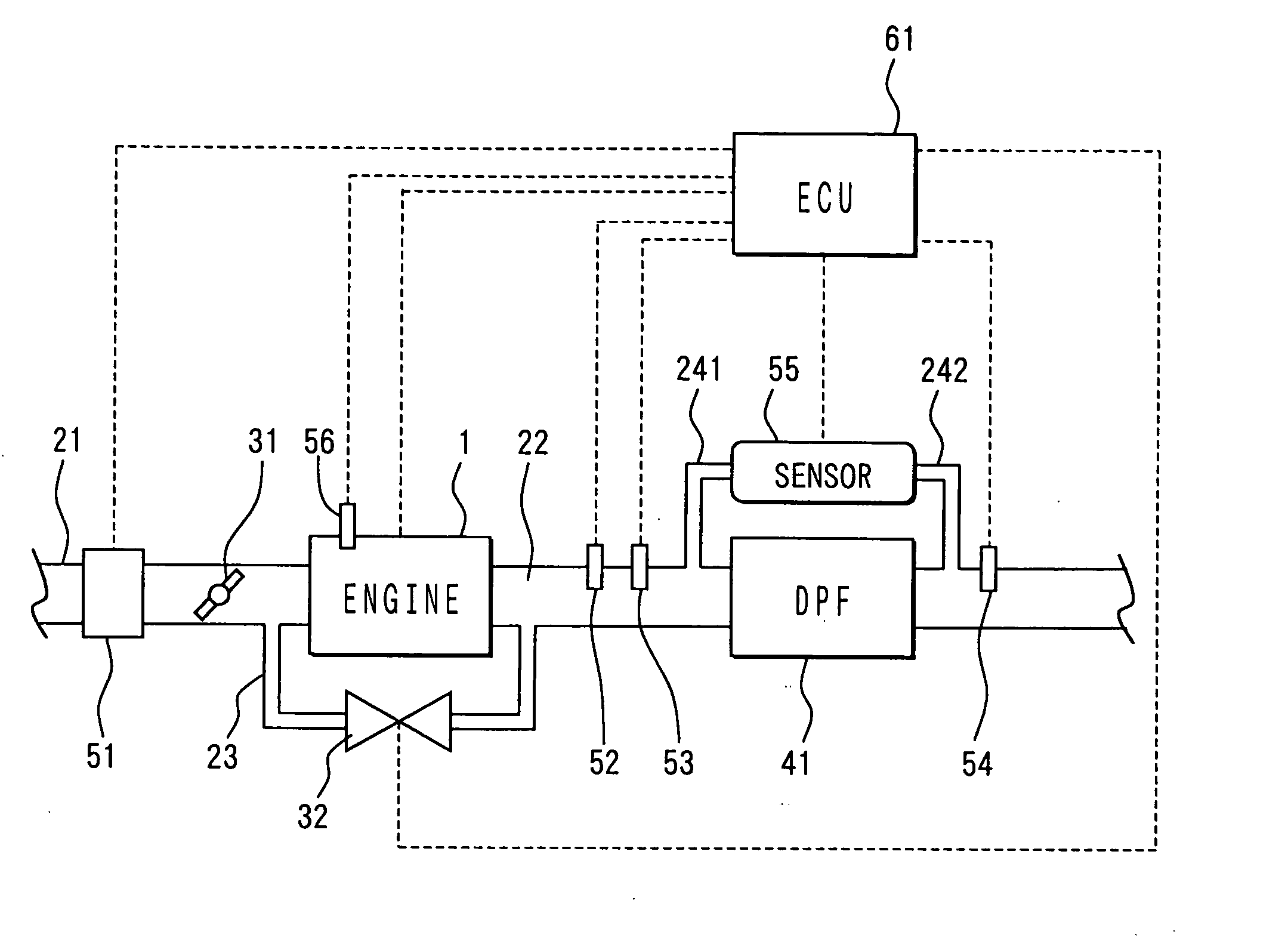
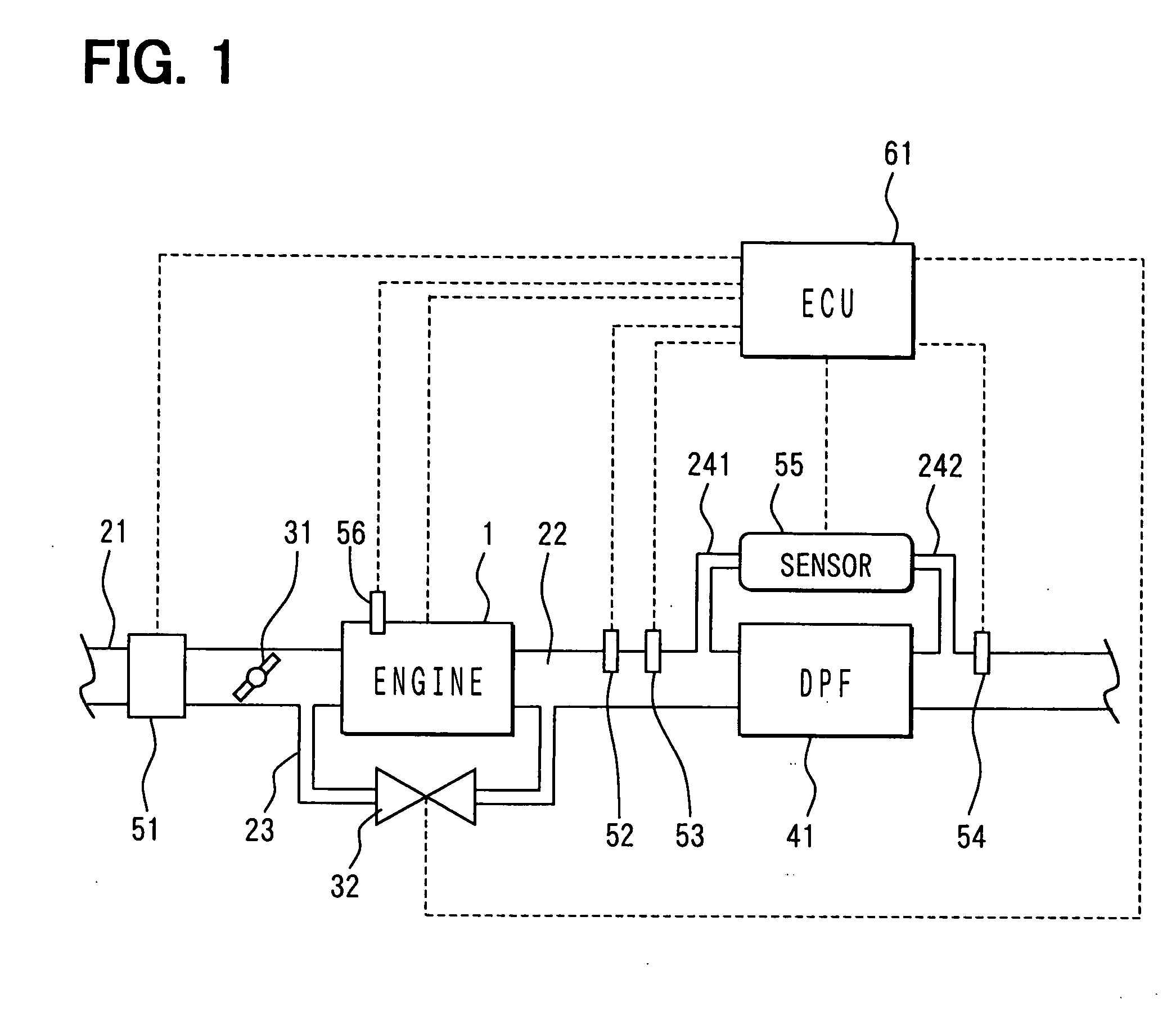
[0038] An embodiment of the present invention will be described with reference to the accompanying drawings. FIG. 1 shows an entire structure of a diesel engine system (an internal combustion engine) having an exhaust gas cleaning device according to the embodiment of the present invention. The engine 1, which has the exhaust gas cleaning device, is of an exhaust gas recirculation (EGR) type. In the engine 1, an EGR passage 23 connects between an air intake passage 21 and an exhaust gas passage 22 to recirculate a portion of the exhaust gas of the exhaust gas passage 22 to the air intake passage 21. The recirculating amount of the exhaust gas is adjusted by an EGR control valve 32, which is provided in the EGR passage 23.

[0039] An air flow meter (an intake air flow sensor) 51 is arranged in the air intake passage 21 to measure the amount of intake air supplied to the engine 1. The air flow meter 51 is of a generally known type, which indicates the measured amount of intake air as a...


PUM

PropertyMeasurementUnit
output poweraaaaaaaaaa
temperatureaaaaaaaaaa
gas temperature sensingaaaaaaaaaa

Abstract

In an engine, when it is determined that catalyst, which is held on a filter substrate of a particulate filter, is not in an active state, an ECU executes a fuel injection for mainly obtaining an engine power near a top dead center of a crank. Then, the ECU executes a subsequent fuel injection after lapse of a sufficient injection interval, which does not cause misfiring, to increase the temperature of exhaust gas outputted from the engine. In this way, the temperature of the filter is rapidly increased.

Description

CROSS REFERENCE TO RELATED APPLICATION [0001] This application is based on and incorporates herein by reference Japanese Patent Application No. 2004-141766 filed on May 12, 2004 and Japanese Patent Application No. 2005-053500 filed on Feb. 28, 2005. BACKGROUND OF THE INVENTION [0002] 1. Field of the Invention [0003] The present invention relates to an exhaust gas cleaning device having a particulate filter for an internal combustion engine. [0004] 2. Description of Related Art [0005] Exhaust particulate matter (PM), which is contained in exhaust gas of a diesel engine, is considered as a major environmental issue, and it has been proposed to install a diesel particulate filter (DPF) for collecting the PM in the diesel engine. The DPF is periodically regenerated by combusting and removing the collected PM to recover its performance for collecting the PM. The combustion of the PM normally requires the sufficiently high temperature of the DPF. However, in some cases, the combustion of ...

Claims


Application Information

Patent Timeline
Patent Type & Authority Applications(United States)
IPC IPC(8): B01D46/42B01D53/94F01N3/02F01N3/035F01N3/08F01N3/20F01N3/24F02D41/02F02D41/14F02D41/40
CPCF01N3/035Y02T10/26F01N2430/085F02D31/008F02D41/0245F02D41/025F02D41/027F02D41/029F02D41/1446F02D41/1448F02D41/401F02D41/402F02D41/403F02D41/405F02D2200/0812Y02T10/44F01N2430/08Y02T10/12Y02T10/40
Inventor OKUGAWA, SHINICHIROKOJIMA, KAZUOHARAGUCHI, HIROSHI
Owner DENSO CORP
Why Eureka
Try Eureka