Battery charging control

a charging control and battery technology, applied in the direction of electric vehicles, safety/protection circuits, transportation and packaging, etc., can solve the problems of high thermal dissipation, control components cannot maintain their functionality, and the charging control is difficult to realize, so as to achieve low thermal dissipation, the battery is empty, and the charge is reliably charged

Inactive Publication Date: 2005-11-17
NOKIA CORP
View PDF1 Cites 11 Cited by
  • Summary
  • Abstract
  • Description
  • Claims
  • Application Information

AI Technical Summary

Benefits of technology

[0017] It is an advantage of the invention that it enables an empty battery to be charged reliably and at the same time with a low thermal dissipation. The reliability is achieved with the stable voltage provided to the control component by the energy storage component. A low thermal dissipation can be ensured, since the control component is no longer dependent on a direct voltage supply from the charging component. This allows closing a switching element connecting the battery to the charging element completely also when charging an empty battery. When the charging current is not limited, the thermal dissipation will be much lower due to the lower potential difference between the charger output and the battery input.
[0018] Even though the invention is of particular advantage when charging an empty battery, it is understood that the energy storage component can be employed as well for providing a supply voltage to the control component when charging partially or fully charged batteries. In case the voltage across the battery is high enough, the voltage provided by the charging component does not drop when it is connected to the battery. In this case, the energy storage component can therefore also be loaded while the charging component is connected to the battery.
[0019] In one embodiment of the invention, a battery charging control circuit comprises moreover an additional switching element associated to the energy storage component. This additional switching element is adapted to connect the energy storage component to the charging component and to disconnect the energy storage component from the charging component, respectively. The additional switching element thus enables an adjustment of the loading of the energy storage component.
[0020] In one embodiment of the invention, the additional switching element is controllable, for example by the control component. The additional switching element might comprise to this end for example a controllable operational amplifier or a controllable simple switch. Such a controllable switch can be realized for instance with a transistor, like a MOSFET. The additional switching element might also comprise an operational amplifier and a switch connected between the operational amplifier and the energy storage component. The control component may then be able to cause the energy storage component to be loaded at least in between the charging periods by controlling the additional switching element. The loading via the additional switching element may depend in addition on the presence of a minimal voltage provided by the charging component. The additional switching element ensures that a leakage current from the energy storage component is minimized while the energy storage component is not loaded.
[0021] In another embodiment of the invention, the additional switching element does not require any control, but connects the energy storage component to the charging component and disconnects the energy storage component from the charging component depending on the voltage currently provided by the charging component and the voltage across the energy storage component. Such an additional switching element can comprise for example a diode. In this case, the energy storage component is always loaded when the voltage provided by the charging component is higher than the diode threshold voltage plus the voltage across the energy storage component. If voltage provided by the charging component is smaller, the diode automatically prevents a discharge of the energy storage component to the charging component.
[0022] The energy storage component may comprise for example a capacitor or a small battery. Also a combined use of a capacitor and a small battery as energy storage component is possible. For example, in case the main battery has enough voltage, it may be used for providing the control component with a supply voltage. In case the main battery is flat, then a small back-up battery is used for providing the control component with a supply voltage. This small back-up battery may be for instance a battery which is mainly used to run a ‘real-time clock’. In case the small back-up battery is flat as well, then the capacitor is used for providing the control component with a supply voltage. The capacitor might also be needed if a back-up battery is available, but not able to be loaded fast enough to start the main battery charging.

Problems solved by technology

A charging control is very difficult to realize, however, if the battery voltage is very low.
When the supply voltage provided by the charger drops to a very low value, the control component cannot maintain its functionality.
This approach has the disadvantage, though, that it results in a high thermal dissipation whenever the battery 18 is basically empty.
Such a high thermal dissipation can lead to a high temperature in the device comprising the battery 18 and the battery charging control circuit 11, which may cause reliability problems in the components of the device.
High temperatures and high voltages are in particular an increasing problem when aiming at downscaling silicon processes used in chips which comprises the battery charging control circuit 11.

Method used


Image

  • Battery charging control
  • Battery charging control
  • Battery charging control

Examples


Embodiment Construction

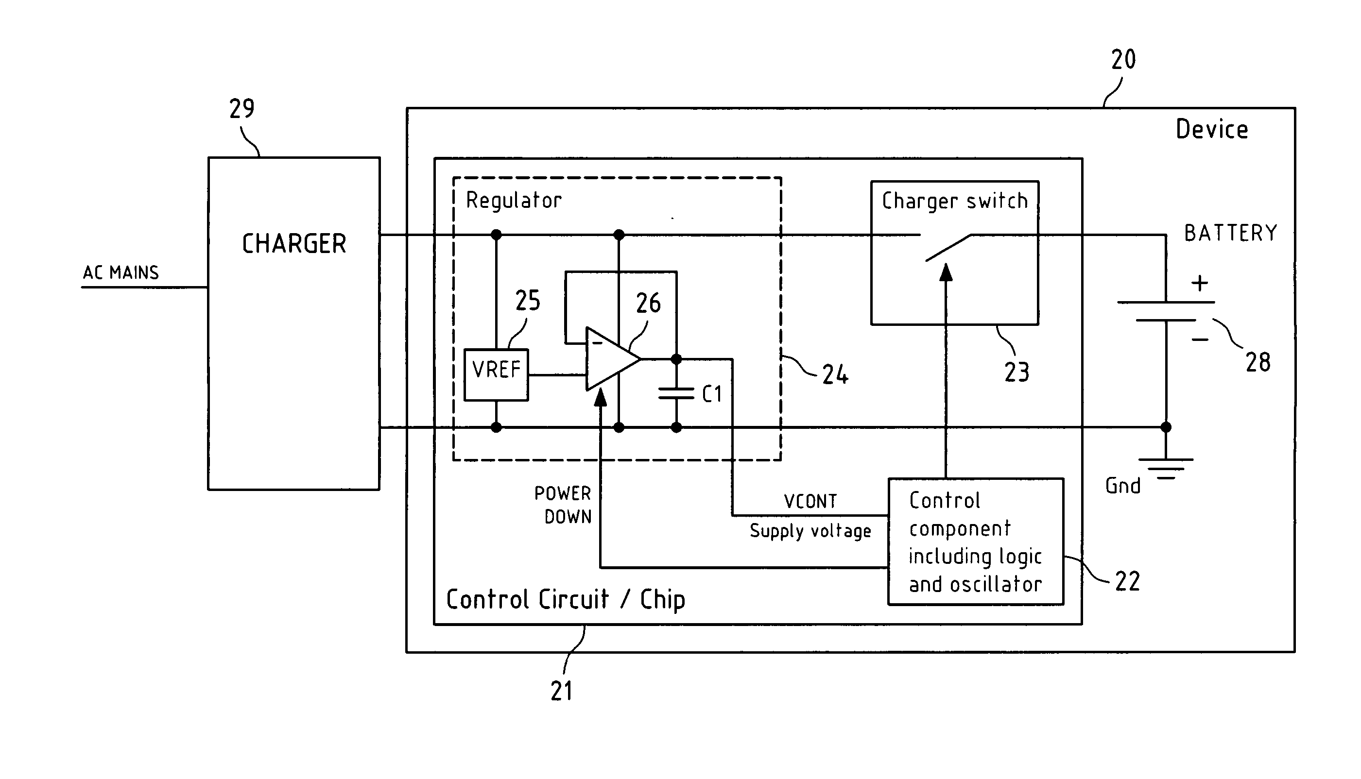
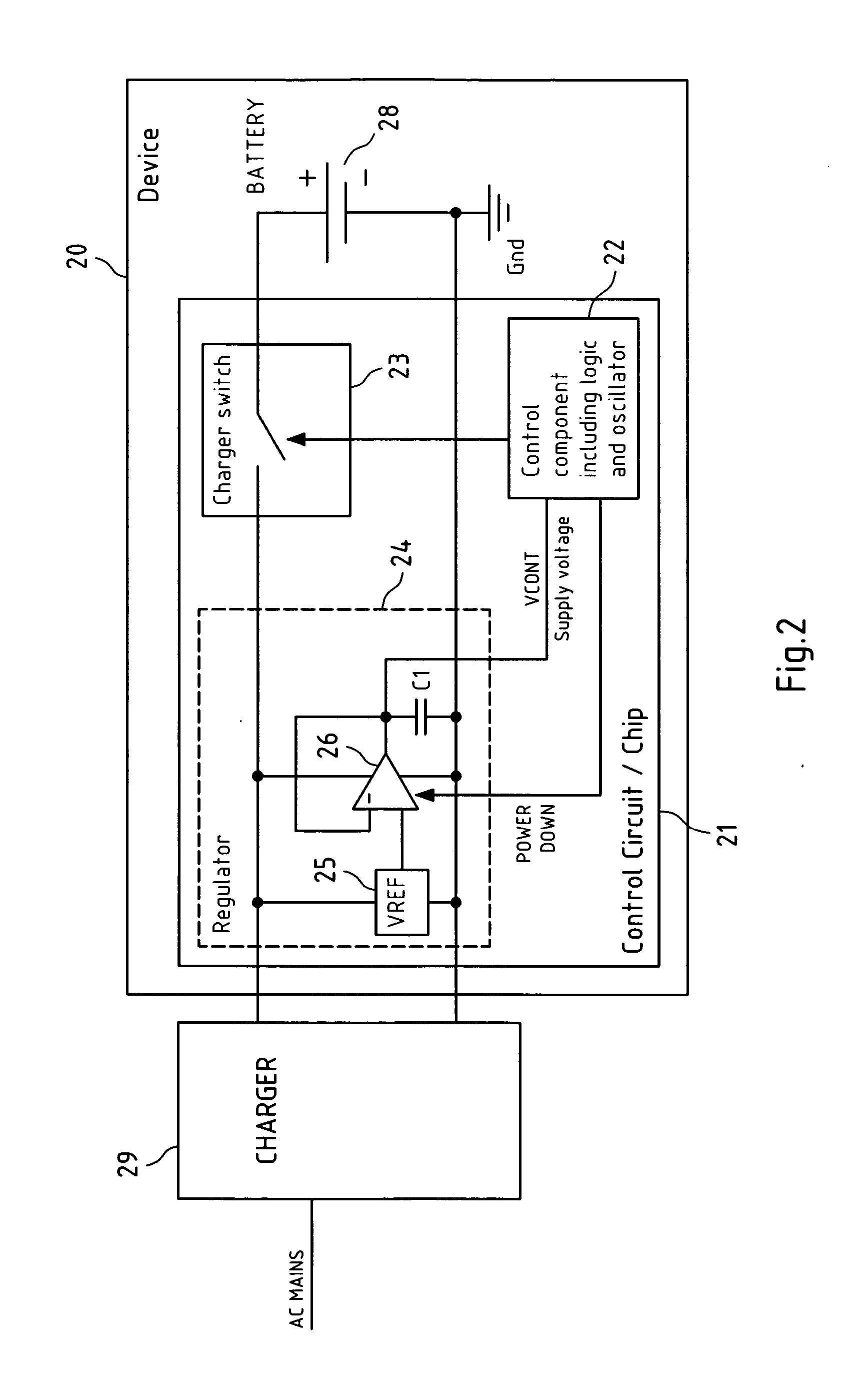
[0037]FIG. 2 is a schematic block diagram of a system for charging a rechargeable battery. In this system, a control component of a battery charging control circuit is provided with a supply voltage in accordance with an embodiment of the invention.

[0038] The system comprises an electronic device 20 which is supplied with power by a rechargeable battery 28. The system further comprises a charger 29 for charging the battery 28. For charging the battery 28, the charger 29 is connected on the one hand to the AC mains, and on the other hand to the electronic device 20.

[0039] The electronic device 20, which can be for example a mobile phone, comprises besides the rechargeable battery 28 a battery charging control circuit 21. The battery charging control circuit 21 may be integrated on a chip and includes a control component 22, a charger switch 23 and a linear regulator 24. The control component 22 comprises a logic realizing a state machine, which is run by a clock signal. The clock s...


PUM


Abstract

The invention relates to a battery charging control circuit for controlling a charging of a rechargeable battery by means of a charging component. The battery charging control circuit comprises a switching element, a control component and an energy storage component. The switching element is adapted to connect a battery to a charging component and to disconnect the battery from the charging component. The control component is adapted to control the switching element. The energy storage component is arranged to be loaded by the charging component and to provide a voltage across the energy storage component as a supply voltage to the control component. The invention relates equally to a electronic device comprising such a circuit and to a method of providing a power supply to a control component of such a circuit.

Description

FIELD OF THE INVENTION [0001] The invention relates to a battery charging control circuit for controlling a charging of a rechargeable battery by means of a charging component. The invention relates equally to a device comprising such a battery charging control circuit and to a method of providing a power supply to a control component of a battery charging control circuit, which control component controls charging a battery with power supplied by a charging component. BACKGROUND OF THE INVENTION [0002] The charging of a rechargeable battery by means of a charging component is frequently controlled by a control circuit, in order to enable optimized charging cycles. A charging component is a component which outputs a suitable voltage for the charging, in particular a component which converts an alternating current (AC) voltage provided by AC mains to a suitable direct current (DC) voltage. The battery charging control circuit may be integrated for instance in the electronic device for...

Claims


Application Information

Patent Timeline
Patent Type & Authority Applications(United States)
IPC IPC(8): H02J7/00
CPCH02J7/0031H02M2001/0006H02J2007/0059H02J7/0052H02J2207/20H02M1/0006H02J7/00
Inventor KUIRI, TAPIO
Owner NOKIA CORP
Why Eureka
Try Eureka