Wavelength insensitive integrated optic polarization splitter

a splitter and wavelength-sensitive technology, applied in the direction of optical waveguide light guide, optical fibre with multi-layer core/cladding, instruments, etc., can solve the problems of polarization dependent performance, cumbersome implementation of bulk optics, and difficult if not impossible to compensate both simultaneously

Active Publication Date: 2005-11-17
MASSACHUSETTS INST OF TECH
View PDF3 Cites 29 Cited by
  • Summary
  • Abstract
  • Description
  • Claims
  • Application Information

AI Technical Summary

Problems solved by technology

Since most integrated optic components are sensitive to both propagation velocity and guide-to-guide coupling, these effects result in polarization dependent performance, a result that is not compatible with the random polarization state emanating from the standard single mode fiber used in telecom applications.
However, while one or the other of these effects may be compensated in this manner for a particular device, as the index contrast increases it becomes difficult if not impossible to compensate both simultaneously in a manner that applies to all devices on the chip.
While such an approach, commonly referred to as a “polarization diversity” scheme, is feasible, when implemented with bulk optics it is also cumbersome.
Aligning PM fibers is difficult and expensive.
However, most of the devices proposed to date rely on the coupling of a pair of waveguide modes.
Further, such approaches are very sensitive to fabrication errors.
It has been proposed and demonstrated that a polarization splitter based on mode evolution can be formed, however, this approach has the disadvantage of requiring multiple waveguide materials.

Method used


Image

  • Wavelength insensitive integrated optic polarization splitter
  • Wavelength insensitive integrated optic polarization splitter
  • Wavelength insensitive integrated optic polarization splitter

Examples


Embodiment Construction

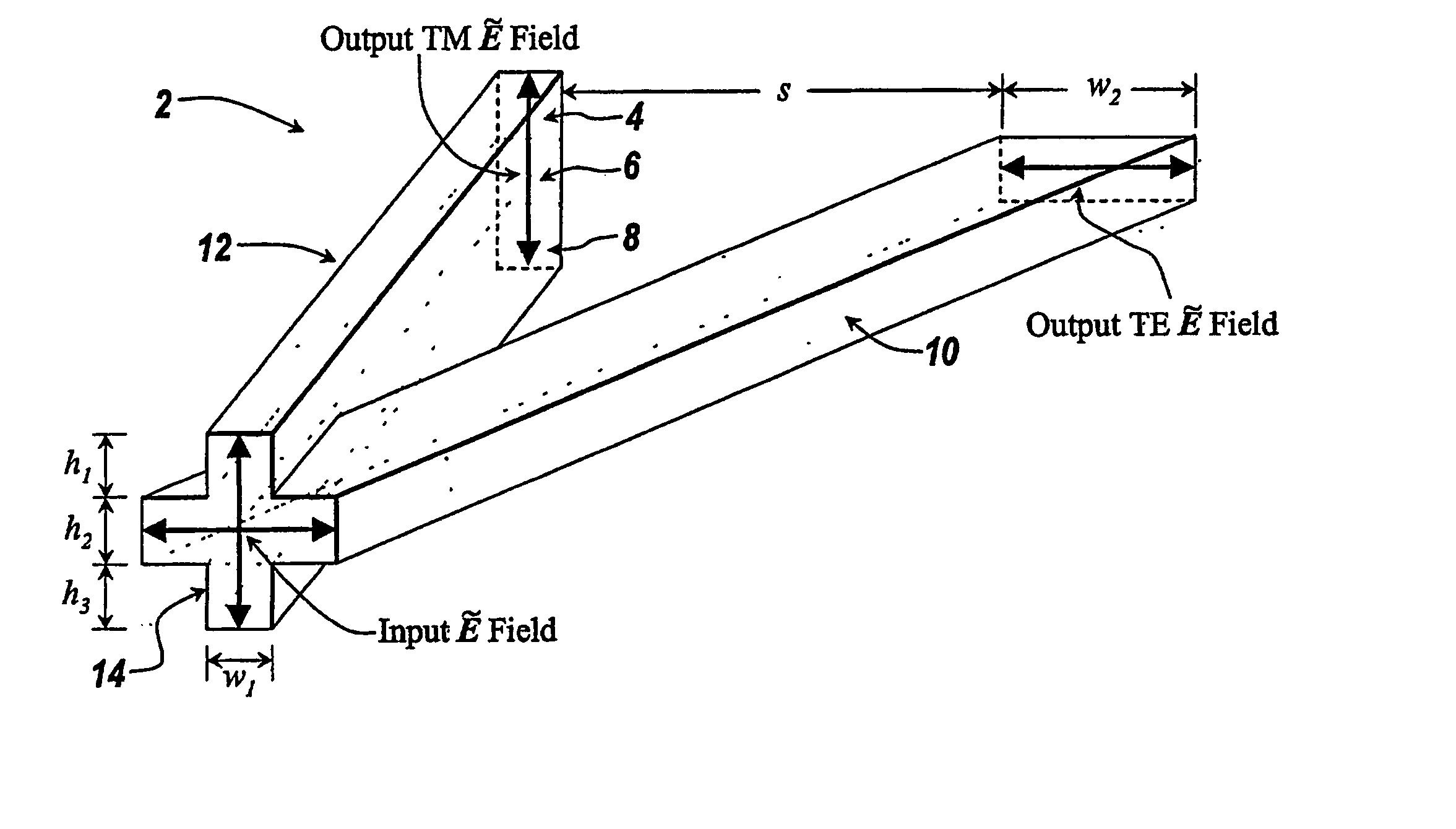
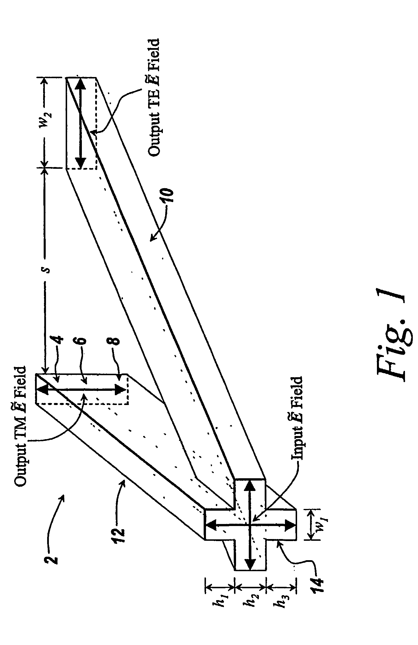
[0024] The polarization splitter of the invention is constructed from the intersection or near intersection of a pair of waveguides. The zone in which the waveguides are in closest proximity is the splitter input and the zone in which they are at their greatest separation is the splitter output. For the device to efficiently separate the polarization states, the fundamental TE (or quasi TE) mode of the combined structure at the device input must evolve into the fundamental mode of one of the guides, denoted the TE guide, while the fundamental TM (or quasi TM) mode evolves into the fundamental mode of the other guide, denoted the TM guide. For this to occur, the TM mode of the TM guide must be more strongly guided (have a higher effective index) than the TM mode of the TE guide. Similarly, the TE mode of the TE guide must be more strongly guided than the TE mode of the TM guide.

[0025] The evolution of the waveguide acts as a perturbation to the mode structure inducing coupling among...


PUM


Abstract

An integrated optic polarization splitter, includes a pair of waveguide elements with a first waveguide element having horizontal orientation and a second waveguide element having a vertical orientation formed from a plurality of waveguide core layers. The first and second waveguide elements are intersected or nearly intersected at one end of the structure and separated at the other end of the structure and the transition there between is made to be adiabatic. The waveguide elements receive an optical signal having both a TE component and a TM component. The TE component propagates along the horizontally oriented waveguide element and the TM component propagates along the vertically oriented waveguide element.

Description

PRIORITY INFORMATION [0001] This application claims priority from provisional application Ser. Nos. 60 / 422,413 filed Oct. 30, 2002, and 60 / 478,767 filed Jun. 16, 2003, incorporated herein by reference in their entirety.BACKGROUND OF THE INVENTION [0002] The invention relates to the field of integrated optic polarization splitters, and in particular to an integrated optic polarization splitter based on the intersection or near intersection of horizontally and vertically oriented waveguides. [0003] As the prevalence of fiber optic communication grows, the demand for more intricate processing of optical signals continues to increase. Since integrated optic devices allow for integration of many optical functions on a chip, integrated optic approaches will likely fill the demand for more intricate optical signal processing. However, in order to improve the functionality and reduce the cost per function the density of components on the chip must increase. [0004] For a given wavelength, th...

Claims


Application Information

Patent Timeline
Patent Type & Authority Applications(United States)
IPC IPC(8): G02B5/18G02B6/126G02B6/27G02B6/28G02B27/28G02B27/42
CPCG02B6/126G02B6/2726G02B27/283G02B6/2843G02B6/2773G02B6/02
Inventor WATTS, MICHAEL R.
Owner MASSACHUSETTS INST OF TECH
Why Eureka
Try Eureka