Voltage conversion device, voltage conversion method, and computer-readable recording medium containing program causing computer to execute voltage conversion

a voltage conversion and computer-readable technology, applied in adaptive control, pulse technique, instruments, etc., can solve problems such as the variation of the follow-up property of output voltage vm with respect to voltage control value vdccom

Inactive Publication Date: 2005-11-17
TOYOTA JIDOSHA KK
View PDF12 Cites 37 Cited by
  • Summary
  • Abstract
  • Description
  • Claims
  • Application Information

AI Technical Summary

Benefits of technology

[0051] Preferably in the program recorded on a computer-readable recording medium, the third substep includes the step of calculating the conversion ratio required for conversion of the output voltage into a reference voltage where the follow-up property is equal to the reference property, and the step of multiplying the preliminary switching duty ratio by the conversion ratio to calculate a switching duty ratio.
[0052] In accordance with the present invention, the direct current voltage from a DC power supply can be converted into the output voltage with the follow-up property of the output voltage to the designated voltage in feedback control kept constant.

Problems solved by technology

As a result, the problem of variation in the follow-up property of output voltage Vm with respect to voltage control value Vdccom will occur.

Method used


Image

  • Voltage conversion device, voltage conversion method, and computer-readable recording medium containing program causing computer to execute voltage conversion
  • Voltage conversion device, voltage conversion method, and computer-readable recording medium containing program causing computer to execute voltage conversion
  • Voltage conversion device, voltage conversion method, and computer-readable recording medium containing program causing computer to execute voltage conversion

Examples


first embodiment

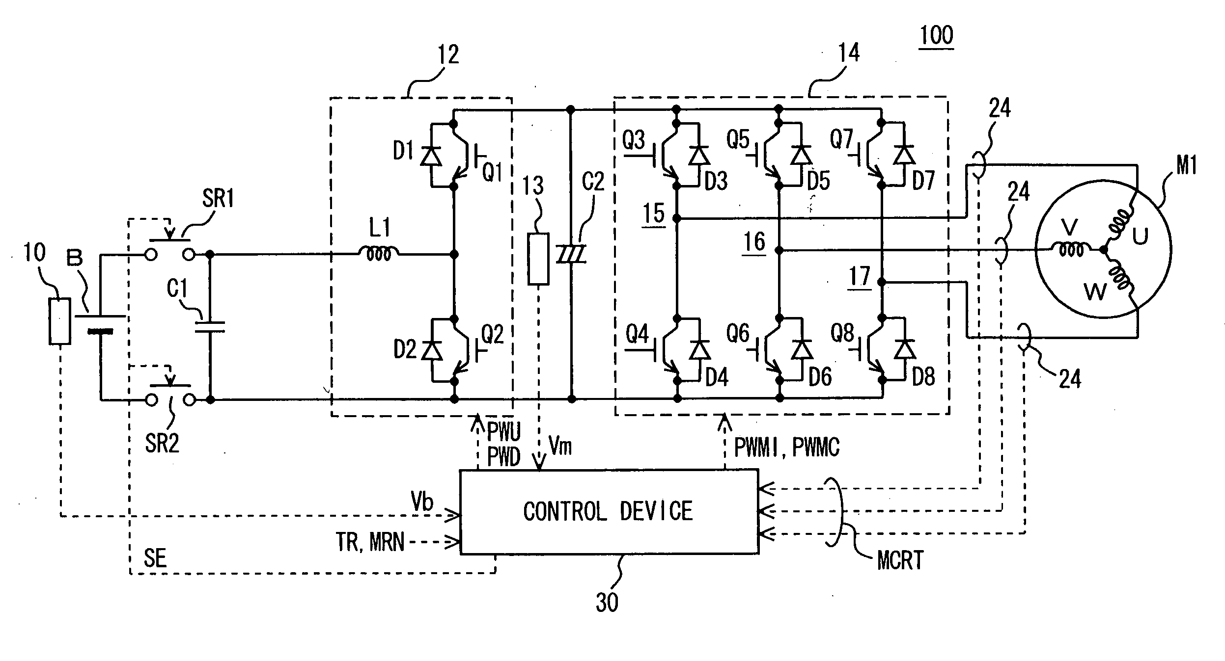
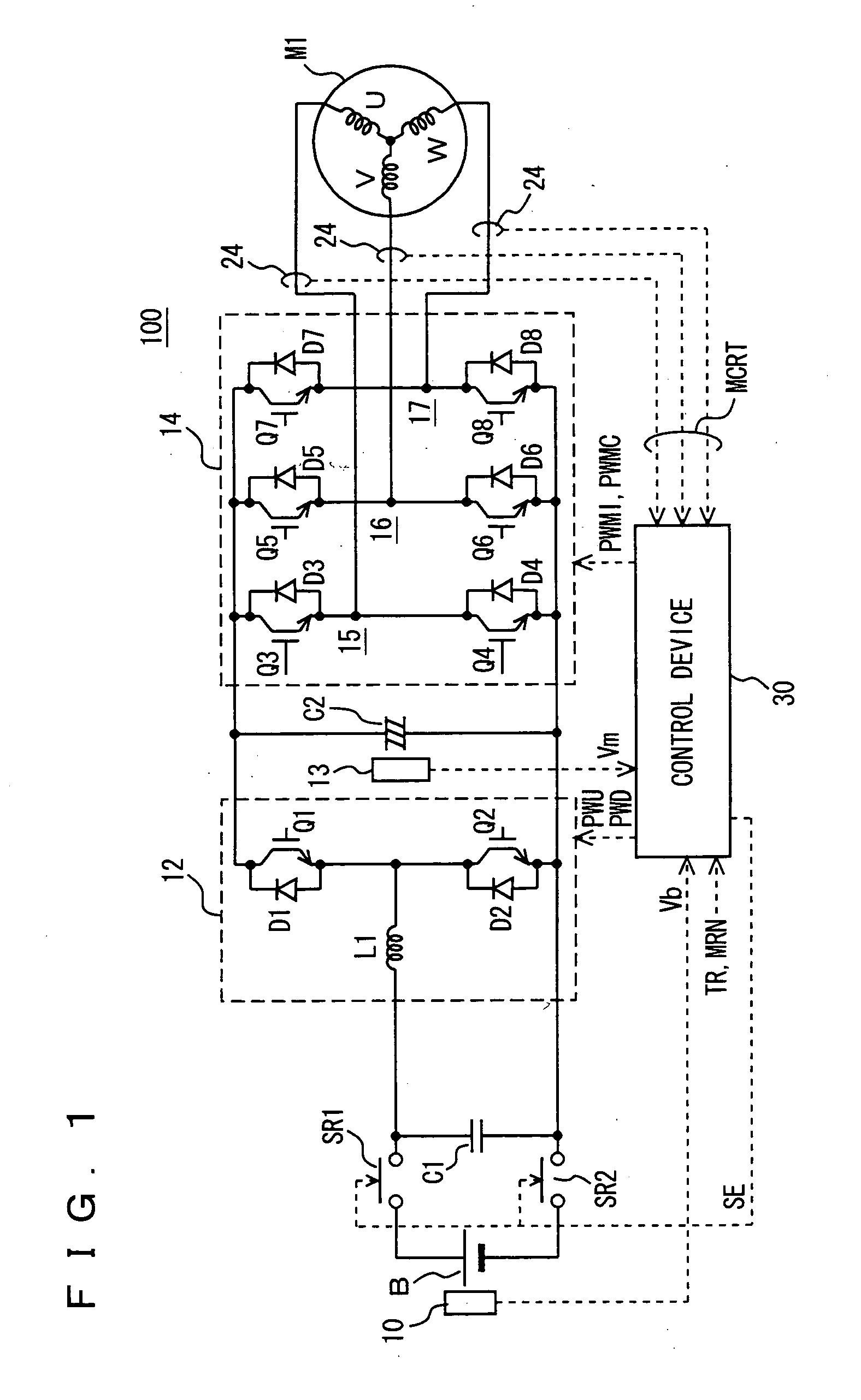
[0077] Referring to FIG. 1, a motor driver 100 including a voltage conversion apparatus according to a first embodiment of the present invention includes a DC power supply B, voltage sensors 10 and 13, system relays SR1 and SR2, capacitors C1 and C2, a voltage-up converter 12, an inverter 14, a current sensor 24, and a control device 30.

[0078] An alternating current motor M1 is a drive motor to generate torque to drive the driving wheel of a hybrid vehicle or electric vehicle. Alternatively, the motor may be incorporated in a hybrid vehicle with the capability of a generator driven by an engine, and operating as a motor for the engine to allow, for example, engine starting.

[0079] Voltage-up converter 12 includes a reactor L1, NPN transistors Q1 and Q2, and diodes D1 and D2. Reactor L1 has one end connected to a power supply line of DC power supply B, and its other end connected at an intermediate point of NPN transistor Q1 and NPN transistor Q2, i.e., between the emitter of NPN tr...

second embodiment

[0160] Referring to FIG. 10, a motor driver 100A including a voltage conversion apparatus according to a second embodiment of the present invention differs from motor driver 100 only in that a control device 30A is provided instead of control device 30 of motor driver 100.

[0161] Referring to FIG. 11, control device 30A differs from control device 30 only in that a motor torque control means 301A is provided instead of motor torque control means 301 of control device 30.

[0162] Motor torque control means 301A generates and provides to inverter 14 a signal PWMI through a method identical to that of motor torque control means 301, and generates and provides to voltage-up converter 12 a signal PWU for controlling NPN transistors Q1 and Q2 of voltage-up converter 12 through a method that will be described afterwards.

[0163] Referring to FIG. 12, motor torque control means 301A differs from motor torque control means 301 only in that a feedback voltage control value calculation unit 52A ...

third embodiment

[0194] Referring to FIG. 15, a motor driver 100B including a voltage conversion apparatus according to a third embodiment of the present invention differs from motor driver 100 only in that a control device 30B is provided instead of control device 30 of motor driver 100.

[0195] Referring to FIG. 16, control device 30B differs from control device 30 only in that a motor torque control means 301B is provided instead of motor torque control means 301 of control device 30.

[0196] Motor torque control means 301B generates a signal PWMI by a method identical to that of motor torque control means 301, and also generates signal PWU in accordance with the method that will be described afterwards to provide the generated signal PWU to voltage-up converter 12.

[0197] Referring to FIG. 17, motor torque control means 301B differs from motor torque control means 301 only in that a feedback voltage control value calculation unit 52B is provided instead of feedback voltage control value calculatio...


PUM


Abstract

A control device receives an output voltage of a voltage-up converter from a voltage sensor, and calculates a feedback preliminary voltage control value determined by the difference between a voltage control value and the output voltage. The control device corrects the calculated feedback preliminary voltage control value in accordance with the output voltage to calculate a feedback voltage control value where the follow-up property of the output voltage with respect to the voltage control value is equal to a reference property. The control device controls the voltage-up converter using a feedback voltage control value. The voltage-up converter converts a direct current voltage from a DC power supply into the output voltage maintaining the follow-up property of the output voltage with respect to the voltage control value at the reference property.

Description

TECHNICAL FIELD [0001] The present invention relates to a voltage conversion apparatus converting a direct current voltage from a DC power supply into a designated voltage, a voltage conversion method of converting a direct current voltage into a designated voltage, and a computer-readable recording medium with a program recorded thereon to allow a computer to execute control of voltage conversion for converting a direct current voltage into a designated voltage. BACKGROUND ART [0002] Hybrid vehicles and electric vehicles are now attracting considerable attention as automobiles taking into account environmental matters. Some hybrid vehicles are now commercially available. [0003] Such hybrid vehicles employ a DC power supply, an inverter, and a motor driven by the inverter as well as a conventional engine, as the power source. Specifically, power is generated by driving the engine, as well as by the rotation of the motor based on converted alternating voltage, achieved by conversion ...

Claims


Application Information

Patent Timeline
Patent Type & Authority Applications(United States)
IPC IPC(8): H02M3/155H02M3/158H02M5/458H02M7/48H02M7/5395H02P23/06
CPCH02M3/156H02M3/1582H02P23/065H02M7/5395H02M2001/007H02M5/4585B60L15/007H02P23/07H02M1/007Y02T10/64H02M3/139H02M3/155
Inventor YAMADA, KENJI
Owner TOYOTA JIDOSHA KK
Why Eureka
Try Eureka