
Fiber-optic transceiver

a transceiver and fiber optic technology, applied in the direction of electromagnetic repeaters, optical elements, instruments, etc., can solve the problems of loss, loss, and loss of approximately 75% of optical power in communication between two conventional transceivers, so as to reduce the cost of components, reduce the loss of light insertion, and reduce the loss of light reception

Active Publication Date: 2005-11-17
MOOG INC
View PDF11 Cites 17 Cited by
  • Summary
  • Abstract
  • Description
  • Claims
  • Application Information

AI Technical Summary

Benefits of technology

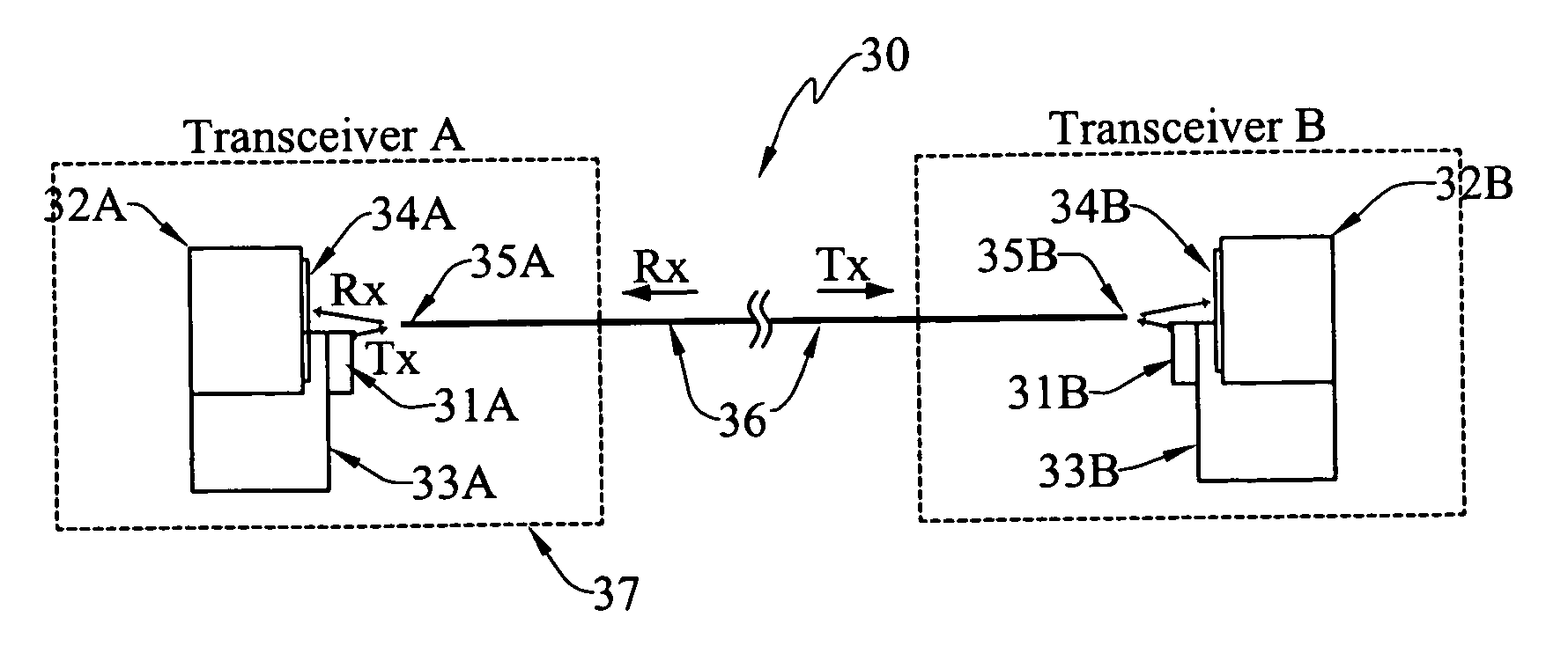
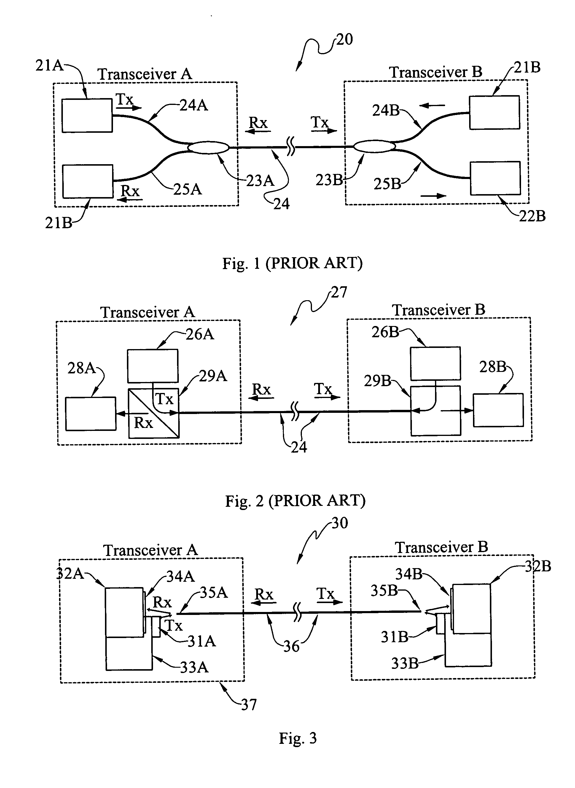
[0007] The present invention relates to fiber-optic transceiver geometries that enable bi-directional optical communication over a single optical fiber. The focus of the present invention is on transceiver configurations and geometries that allow optical coupling from the light source to the optical fiber, and from the optical fiber to the photodetector. The invention provides an improvement over existing technologies. Light insertion losses and light reception losses are reduced. The cost of components is lowered, and the assembly labor is also reduced.
[0021] Another object is to provide an improved fiber-optic transceiver having reduced light source insertion losses and photodetector reception losses.
[0022] Another object is to provide an improved fiber-optic transceiver in which the cost of the various components is lowered, and the assembly labor is reduced.

Problems solved by technology

However, these methods have one common drawback, namely, that at least 50% of the optical power is typically lost in transmitting and receiving the optical signals.
The losses occur because both the coupler and the beamsplitter are only partially transmissive or reflective.
Thus, approximately 75% of the optical power is lost in communicating between two conventional transceivers.

Method used


Image

  • Fiber-optic transceiver
  • Fiber-optic transceiver
  • Fiber-optic transceiver

Examples


Embodiment Construction

[0033] At the outset, it should be clearly understood that like reference numerals are intended to identify the same structural elements, portions or surfaces consistently throughout the several drawing figures, as such elements, portions or surfaces may be further described or explained by the entire written specification, of which this detailed description is an integral part. Unless otherwise indicated, the drawings are intended to be read (e.g., cross-hatching, arrangement of parts, proportion, degree, etc.) together with the specification, and are to be considered a portion of the entire written description of this invention. As used in the following description, the terms “horizontal”, “vertical”, “left”, “right”, “up” and “down”, as well as adjectival and adverbial derivatives thereof (e.g., “horizontally”, “rightwardly”, “upwardly”, etc.), simply refer to the orientation of the illustrated structure as the particular drawing figure faces the reader. Similarly, the terms “inw...


PUM


Abstract

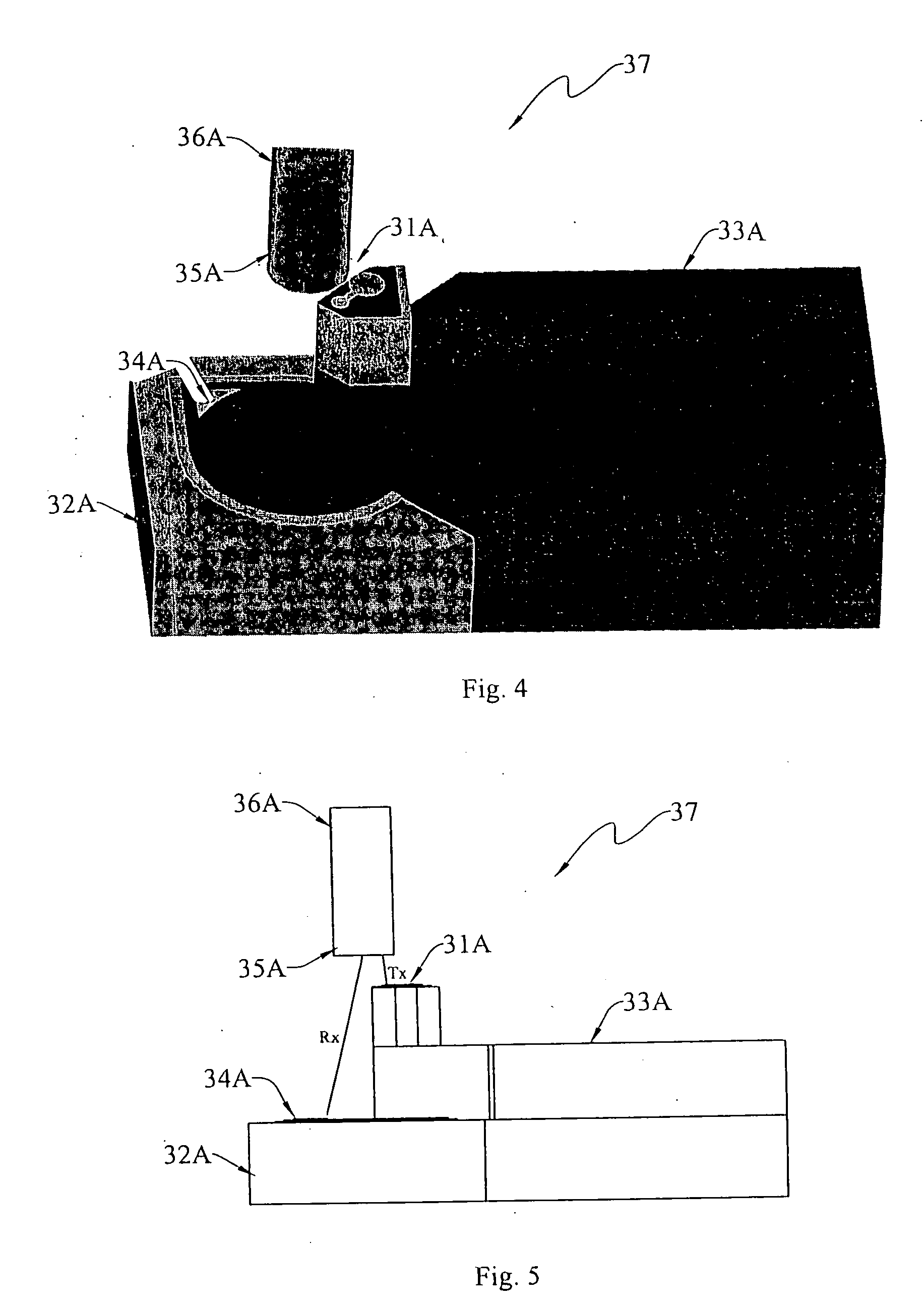
A fiber optic transceiver (37) is adapted for use in transmitting and receiving optical signals in a fiber-optic network (30). The improved transceiver comprising: a multi-mode optical fiber (36) having a longitudinal axis (x-x) and having a proximal end (35). The fiber is adapted to convey optical signals in either direction therealong. A photodetector (32) is arranged in longitudinally-spaced relation to the fiber proximal end. The photodetector has a sensitive surface (34) operatively arranged to receive light energy exiting the fiber through the proximal end. A light source (31) is arranged between the fiber proximal end and the photodetector surface. The light source is arranged to selective emit light energy into the fiber through the proximal end.

Description

TECHNICAL FIELD [0001] The present invention relates generally to fiber-optic signal transmitting and receiving devices, and, more particularly, to improved fiber-optic transceivers that are adapted for use in transmitting and receiving optical signals in a fiber-optic network. BACKGROUND ART [0002] A device that is capable of both transmitting and receiving optical signals in a fiber-optic network is called a fiber-optic transceiver. There are two operational modes of communication in a bi-directional transceiver: the transmission (Tx) mode, and the reception (Rx) mode. In the Tx mode, a transmitter typically converts an electrical input signal to an optical signal by modulating a laser or light-emitting diode (LED) source. The optical signal is coupled to an optical fiber and transmitted to the optical fiber network. In the Rx mode, a receiver receives an optical signal from the optical network, and converts it into an electrical signal through the use of a photodetector. In a bi-...

Claims


Application Information

Patent Timeline
Patent Type & Authority Applications(United States)
IPC IPC(8): H04B10/00H04B10/24H04B10/29
CPCH04B10/40G02B6/4246
Inventor DUNCAN, MICHAEL P.LO, KANWAI P.VAUGHT, LARRY D.WITHERSPOON, BARRY K.
Owner MOOG INC
Learn More