Blade fixing relief mismatch

a technology of fixing relief and blades, applied in the direction of propulsive elements, propellers, water-acting propulsive elements, etc., can solve the problems of high local radial stress in the front of the disk, uneven axial distribution of radial load on the fixation and disk, and high local radial stress in the disk retaining blades. , to achieve the effect of reducing high local radial stress transfer

Active Publication Date: 2005-11-17
PRATT & WHITNEY CANADA CORP
View PDF20 Cites 10 Cited by
  • Summary
  • Abstract
  • Description
  • Claims
  • Application Information

AI Technical Summary

Benefits of technology

[0009] It is a general aim of the present invention to provide an improved blade and disk interface for a gas turbine engine.
[0010] It is also an aim of the present invention to provide a method for reducing a local contact stress between a disk and a blade.
[0011] It is a further aim of the present invention to provide a method for reducing a local radial stress in a bladed rotor disk assembly.
[0014] In accordance with a further general aspect of the present invention, there is provided a method for reducing high local stress transfer between a gas turbine engine blade fixing and a blade mounting slot of a rotor disk, the method comprising the steps of: a) determining which portion of a full length of the blade fixing and the blade mounting slot is subject to maximal contact stresses, and b) providing a mismatch fit in said portion of maximal stress.

Problems solved by technology

This in turn causes high radial stress in the disk retaining the blades.
A significant portion of the weight of these blades is cantilevered over the front portion of the fixation, which causes an uneven axial distribution of the radial load on the fixation and disk.
This load distribution causes high local radial stress in the front of the disk and high contact forces between the blade and the front of the disk.
Although a number of solutions have been provided to even axial distribution of stress in blades, such as grooves in blade platforms to alleviate thermal and / or mechanical stresses, these solutions do not address the problem of high local radial stress in the disk supporting the blades.
However, such solutions are not applicable to reduce the increased local contact stress produced by the asymmetry of “swept” fans.
In addition, such solutions do not address the problem of high local radial stress in the disk supporting the blades.

Method used


Image

  • Blade fixing relief mismatch
  • Blade fixing relief mismatch
  • Blade fixing relief mismatch

Examples


Embodiment Construction

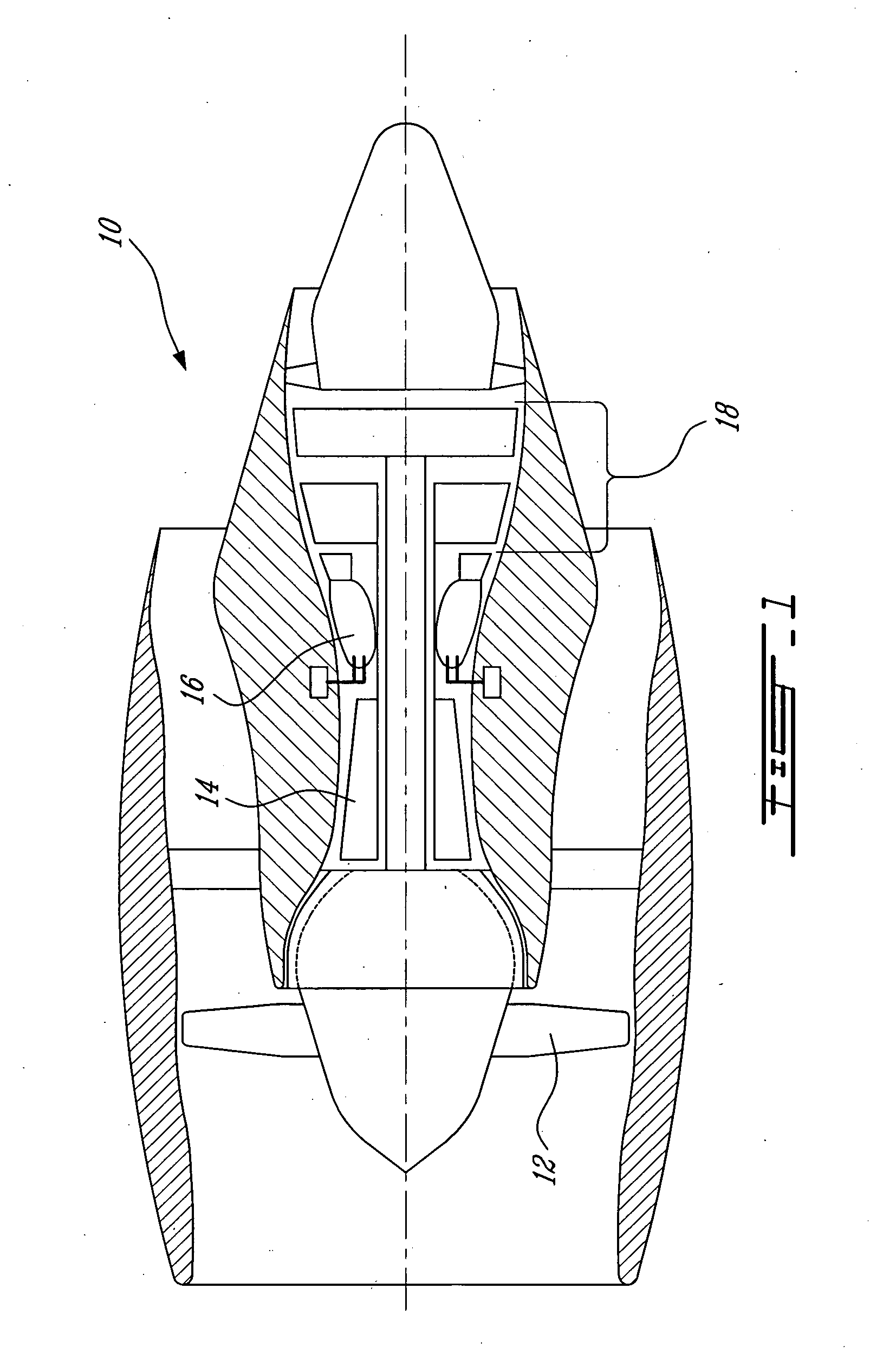
[0020]FIG. 1 illustrates a gas turbine engine 10 of a type preferably provided for use in subsonic flight, generally comprising in serial flow communication a fan 12 through which ambient air is propelled, a multistage compressor 14 for pressurizing the air, a combustor 16 in which the compressed air is mixed with fuel and ignited for generating an annular stream of hot combustion gases, and a turbine section 18 for extracting energy from the combustion gases.

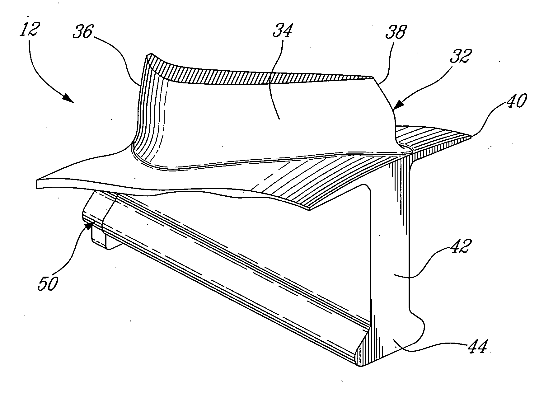
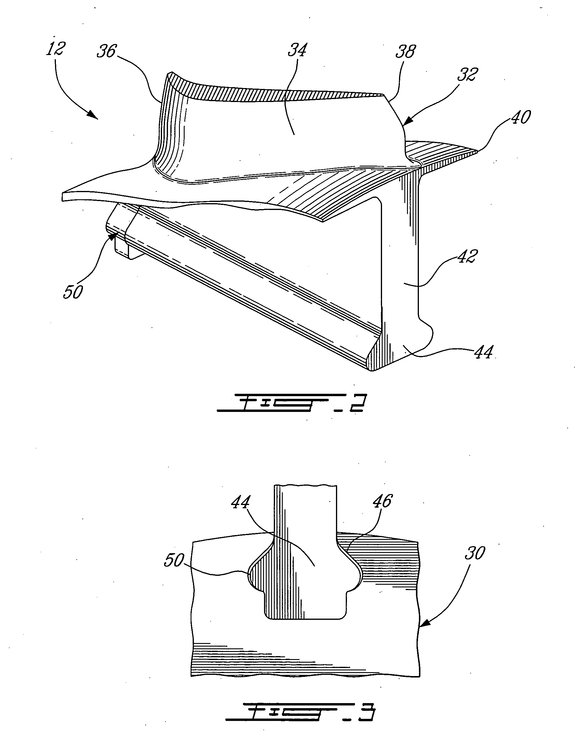
[0021] Referring to FIG. 2, a part of a blade 32 of the fan 12, which is a “swept” fan, is illustrated. Although the present invention applies advantageously to such fans, it is to be understood is can also be used with other types of conventional fans, as well as other types of rotating equipment requiring a smoother axial distribution of radial stress in the disk and in a disk to blade interface including, but not limited to, compressor and turbine rotors.

[0022] Referring to FIGS. 2-3, the fan 12 includes a disk 30 supporti...


PUM

PropertyMeasurementUnit
thicknessaaaaaaaaaa
contact stressaaaaaaaaaa
lengthaaaaaaaaaa

Abstract

A blade fixing and blade mounting slot arrangement for a gas turbine engine has a mismatch fit along a portion of the length of the blade fixing and slot where contact stress would otherwise be maximal.

Description

BACKGROUND OF THE INVENTION [0001] 1. Field of the Invention [0002] The present invention relates to gas turbine engines and, more particularly, to blade and disk interfaces of such engines. [0003] 2. Background Art [0004] Fan rotors can be manufactured integrally or as an assembly of blades around a disk. In the case where the rotor is assembled, the fixation between each blade and the disk has to provide retention against extremely high radial loads. This in turn causes high radial stress in the disk retaining the blades. [0005] In the case of “swept” fans, the blades are asymmetric with respect to their radial axis. A significant portion of the weight of these blades is cantilevered over the front portion of the fixation, which causes an uneven axial distribution of the radial load on the fixation and disk. This load distribution causes high local radial stress in the front of the disk and high contact forces between the blade and the front of the disk. [0006] Although a number o...

Claims


Application Information

Patent Timeline
Patent Type & Authority Applications(United States)
IPC IPC(8): B63H1/20F01D5/30F04D29/32
CPCF01D5/3007F01D5/3092F04D29/322Y10T29/49321Y10T29/49776Y10T29/49995Y10T29/49764
Inventor STONE, PAUL
Owner PRATT & WHITNEY CANADA CORP
Why Eureka
Try Eureka