Microfluidic device, method for testing reagent and system for testing reagent

Inactive Publication Date: 2005-11-17
KONICA MINOLTA SENSING INC
View PDF21 Cites 51 Cited by
  • Summary
  • Abstract
  • Description
  • Claims
  • Application Information

AI Technical Summary

Benefits of technology

[0013] The present invention is directed to solve the problems pointed out above, and therefore, an object of the present invention is to provide a microfluidic device, a method for testing a

Problems solved by technology

Accordingly, positioning of the reagent is far from easy and it is difficult that the reagent is brought to a standstill at a predetermined position correctly and a temperature process using a liquid is performed precisely.
In addition, the use of the three vessels and the capillary imposes limitation on reduction in the size of the appa

Method used


Image

  • Microfluidic device, method for testing reagent and system for testing reagent
  • Microfluidic device, method for testing reagent and system for testing reagent
  • Microfluidic device, method for testing reagent and system for testing reagent

Examples


first embodiment

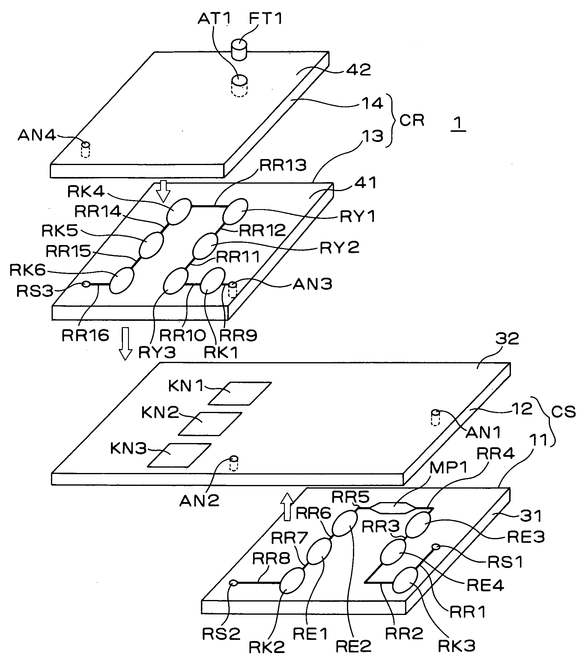
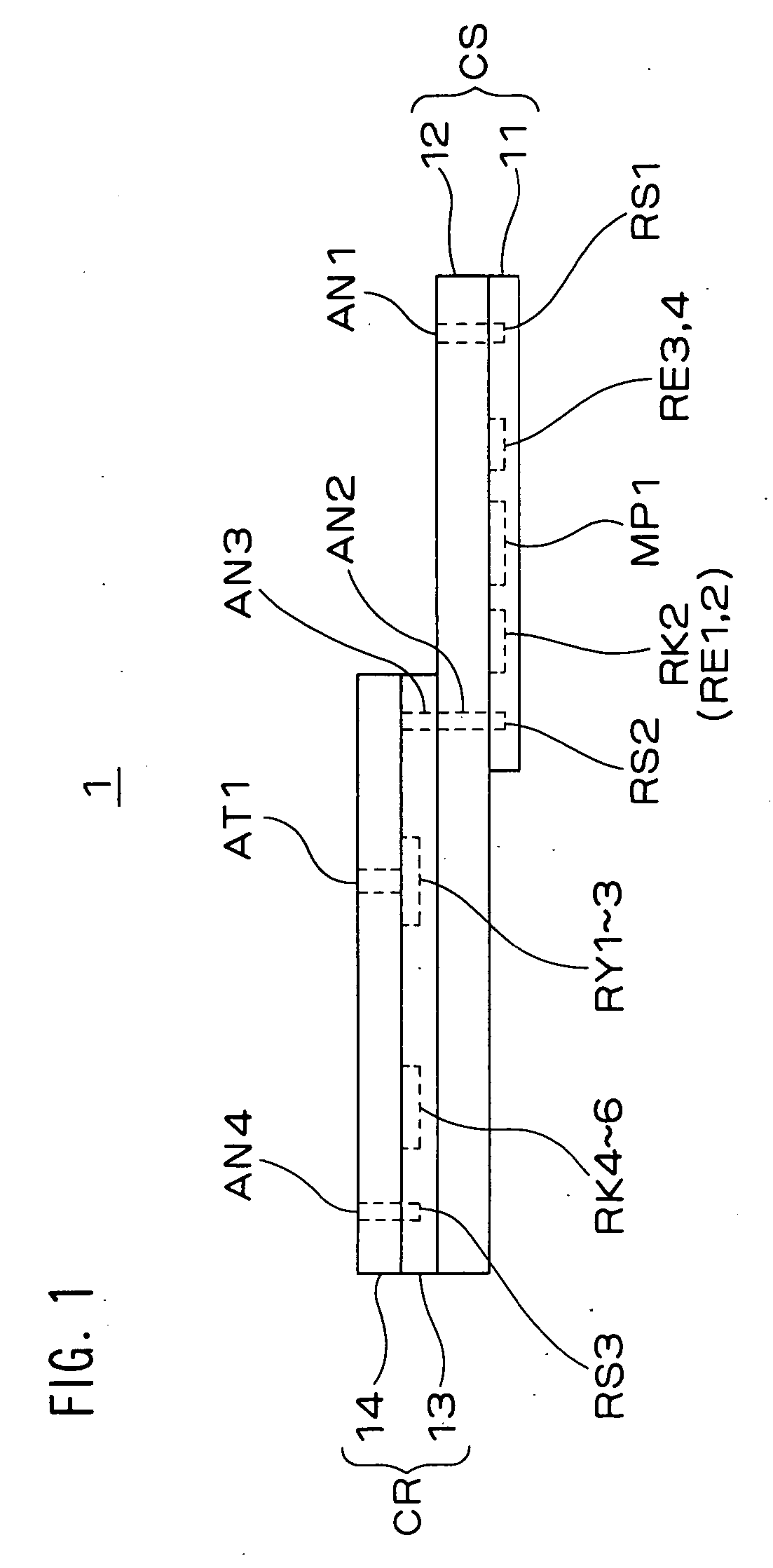
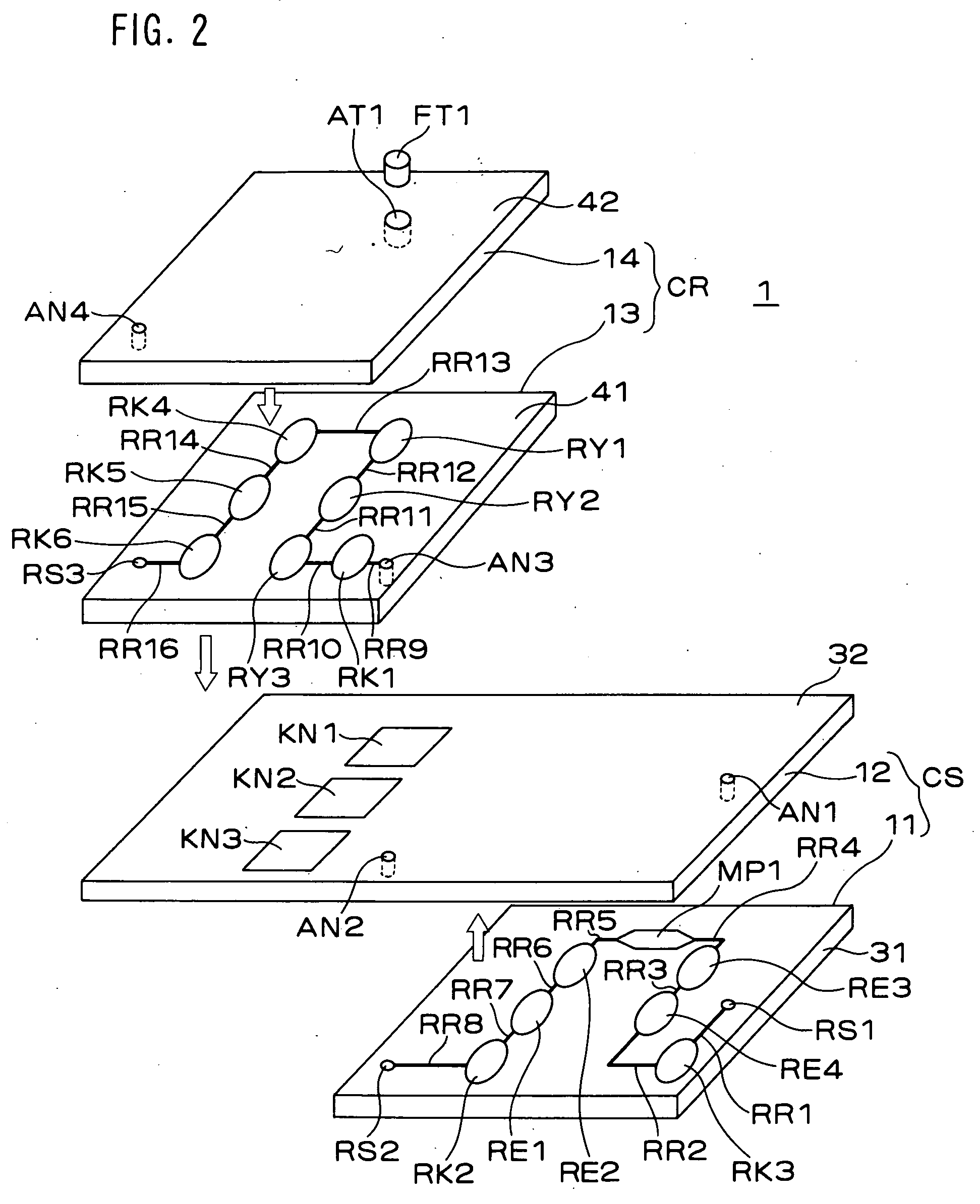
[0043]FIG. 1 is a front view of a microfluidic device 1 according to a first embodiment of the present invention, FIG. 2 is an exploded perspective view of a structure of the microfluidic device 1, FIG. 3 is a plan view of a micropump MP1 shown in FIG. 2, FIG. 4 is a front sectional view of the micropump MP1, FIGS. 5A-5H show an example of a manufacturing process of the micropump MP1, FIGS. 6A and 6B as well as FIGS. 7A and 7B show examples of waveforms of a drive voltage of a piezoelectric element.

[0044] Referring to FIGS. 1 and 2, the microfluidic device 1 includes two chips removably attached to each other. One of the two chips is a chip CS for liquid transport on which the micropump MP1 is mounted, while the other is a chip CR for process into which a reagent (a specimen liquid) is injected for a PCR reaction.

[0045] The liquid transport chip CS includes a pump chip 11 and a glass substrate 12.

[0046] The pump chip 11 has a structure in which the micropump MP1, liquid chambers ...

second embodiment

[0116] In the foregoing first embodiment, the three process chambers RY1-RY3 are individually provided corresponding to the three heating portions KN1-KN3 that are separately provided. In a second embodiment, however, a structure is adopted in which a plurality of temperature areas is provided in one chamber having a constant sectional area.

[0117]FIG. 13 is a diagram showing a structure of a microfluidic device 1B according to the second embodiment of the present invention, mainly by a connection state of chambers therein.

[0118] As shown in FIG. 13, one process chamber RY11 is provided with extending over three heating portions KN1-KN3. Three chambers Y1-Y3 are provided inside the process chamber RY11. The chambers Y1-Y3 are provided at portions corresponding to the heating portions KN1-KN3, respectively. When being heated, the three chambers Y1-Y3 function as temperature areas of the heating portions KN1-KN3, respectively. Each of the three chambers Y1-Y3 has a volume greater tha...

third embodiment

[0122] In the foregoing first and second embodiments, an end portion of the channel RR1 provided in the micropump MP1 side, i.e., the connection chamber RS1 is completely independent of an end portion of the channel RR16 provided in the process chambers RY side, i.e., the connection chamber RS3. In short, the connection chamber RS1 is not in communication with the connection chamber RS3 in the first and second embodiments. Instead, in a third embodiment, a structure is adopted in which the both end portions are in communication with each other and all the channels RR form one closed loop.

[0123]FIG. 14 is a diagram showing a structure of a microfluidic device 1C according to the third embodiment of the present invention, mainly by a connection state of chambers therein.

[0124] As shown in FIG. 14, the microfluidic device 1C includes a liquid transport chip CSC and a process chip CRC.

[0125] The liquid transport chip CSC includes two micropumps MP1-MP2, a liquid chamber RE12, a gas c...


PUM


Abstract

A microfluidic device for performing a test on the reagent includes a fill port formed on the chip to inject the reagent into at least one of the channels, one or more heating portions for performing a test on the reagent injected into the channel, and a micropump. An inside of the micropump and a vicinity of the channel connecting to an inlet and an outlet of the micropump are filled with a drive solution that is driven by the micropump, a gas is sealed between the reagent and the drive solution in the channel to prevent the reagent from contacting the drive solution directly, and the micropump directly drives the drive solution in the forward and backward directions, so that the reagent is repeatedly moved to the test portions through the gas in an indirect manner or is repeatedly passed through the test portions through the gas.

Description

[0001] This application is based on Japanese Patent Application No. 2004-143108 filed on May 13, 2004, the contents of which are hereby incorporated by reference. BACKGROUND OF THE INVENTION [0002] 1. Field of the Invention [0003] The present invention relates to a microfluidic device for distributing a small amount of reagent in channels formed on chips to test the reagent. The present invention is used for, for example, gene amplification by a PCR method. [0004] 2. Description of the Related Art [0005] Conventionally, Japanese Patent No. 3120466 proposes that a capillary is used as a channel for a reagent or a reaction solution for gene amplification by the PCR method. [0006] More specifically, three vessels containing three liquids whose temperatures differ from one another are prepared. The three liquids are adjusted so as to be a heat denaturation temperature (95° C., for example), an annealing temperature (55° C., for example) and a polymerization temperature (75° C., for exam...

Claims


Application Information

Patent Timeline
IPC IPC(8): B01J19/00G01N35/08B01L3/00B01L7/00B81B3/00C12M1/00F04B43/04F04B53/10G01N37/00
CPCB01L3/502715F04B53/1077B01L7/525B01L2200/0673B01L2200/141B01L2300/0645B01L2300/0816B01L2300/087B01L2300/0874B01L2300/0887B01L2400/0439B01L2400/0481B01L2400/0487F04B43/046B01L3/50273
Inventor YAMADA, MASAYUKIMATSUMOTO, TAKESHISANDO, YASUHIROHIGASHINO, KUSUNOKI
Owner KONICA MINOLTA SENSING INC
Why Eureka
Try Eureka