Dental insert and method of tooth restoration

a technology of inserts and teeth, applied in dentistry, medical science, teeth capping, etc., can solve the problems of difficult packing of resins, inability to create good proximal contact, and gaps that are too wide to allow for good proximal contact, etc., to achieve convenient handling and placement, easy sterilization, and convenient individual packaging

Inactive Publication Date: 2005-11-17
COOPERSMITH ALLAN
View PDF11 Cites 31 Cited by
  • Summary
  • Abstract
  • Description
  • Claims
  • Application Information

AI Technical Summary

Benefits of technology

[0024] The present invention overcomes the deficiencies of the prior art in several respects. Because the dental insert is correctly sized to fit between the sloped axial wall and the matrix band, easy and safe and controllable apical pressure creates significant lateral pressure ensuring tight functional and anatomic contacts. Furthermore because said insert is already set and hard and pre-shrunk, the resultant restoration is stronger and harder and better than conventional composite resin restorations. The curved or round surfaces of the dental insert(s) creates a wedge like action to help create tight and anatomic and functional contacts without creating internal stresses of the set restoration which can contribute to fracture and failure.
[0025] Moreover, the dental insert(s) of the present invention are easy to handle and to place, are inexpensive, are easy to sterilize and may be easily individually packaged to retain their sterility. Finally, the insert(s) of the present invention allow for faster, more accurate and predictable and less damaging interproximal contact formation, leading to better results from the dental procedures (e.g. restoring cavities between teeth) that they are intended to facilitate.

Problems solved by technology

Consequently, these resins are difficult to pack into the proximal box of a class two filling sufficiently to drive apart the tooth receiving the filling and the adjacent tooth (or teeth in the case where proximal surfaces at both sides of the tooth are being treated).
Consequently, when a commonly used matrix band is removed from a class 2 filling made with composite material, a gap often remains between the filled tooth and the adjacent tooth.
These gaps are too wide to allow creation of a good proximal contact.
However, problems still remain as resins of this type known to the inventor at this time are not dense enough or compactable enough to entirely solve the open contact problem.
The problem with this instrument and technique is that it is difficult to place adequate pressure with the instrument against the band and often so much pressure is required that the instrument slips or breaks.
Once the composite resin sets around the instrument, it is often difficult for the operator to remove the instrument, and often times the composite resin sets around the undercut of the instrument whose curved surface is usually present to help contour the oval or round curved contact area further preventing an easy removal of said instrument.
The problem with today's composite resins is that no one composite can seal, condense and surface finish properly.
Composites which must be hard and resistant to occlusal forces and wear are not flowable nor seal dentin well.
These rings are uncomfortable, difficult to place, require a special clamp, often dislodge from the teeth or break thereby propelling said ring violently towards the throat which can cause it to be swallowed or aspirated by the patient, or ejecting said ring from the patient's mouth.
This insert must be forced laterally against the proximal tooth which has the following drawbacks of being non efficient, places undue stress on the patient's mouth, is prone to fracture of the insert and often requires a special instrument to engage said insert.
This insert is more likely to slip while applying pressure in a lateral direction and is also more likely to harm the oral tissues than if an instrument is used to compress an insert in an apical direction.
This requires an extra step and raises questions of the exposed interphase between the insert and the composite resin at the restoration's surface.
All of the surfaces of Kurer's dental insert is not entirely smooth nor curved nor rounded, which can lead to internal stress and resultant fracture of the final restoration.
It has the drawbacks however of being softer, less wear resistant, and is not compressible thereby making it unsuitable to establish proper contact with adjacent teeth.

Method used


Image

  • Dental insert and method of tooth restoration
  • Dental insert and method of tooth restoration
  • Dental insert and method of tooth restoration

Examples


Embodiment Construction

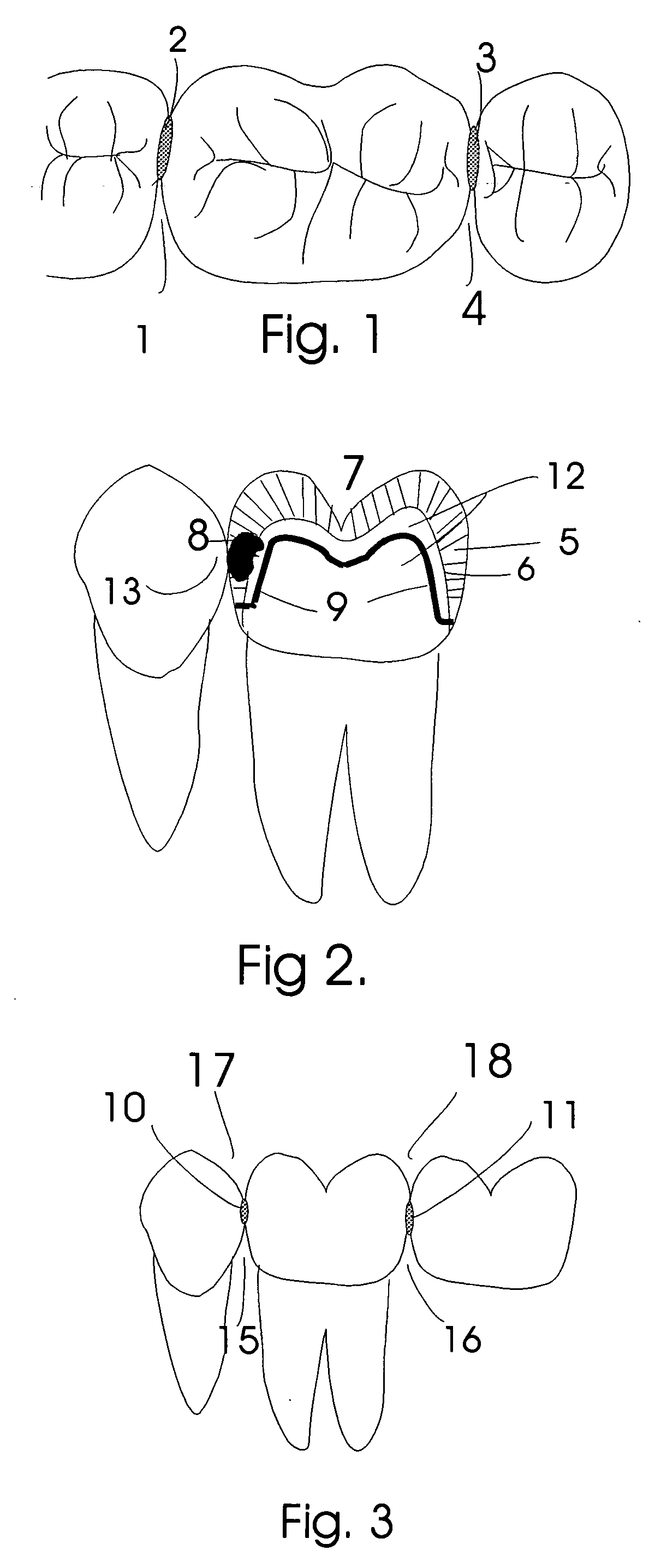
[0056]FIG. 1. demonstrates the position and contour of the interproximal contacts as viewed from the top or occlusal aspect. Note how they are located buccal to the middle of the tooth and therefore creates a more prominent lingual embrasure 1, 4, and a less prominent buccal embrasure 14. 1 refers to the distal lingual embrasure. 4 refers to the mesial lingual embrasure. 2 is the distal occlusal contact area and 3 is the mesial occlusal contact area. The preferred embodiment of the dental insert (s)(not shown but seen in FIG. 6. will be placed into the proximal box (s) to coincide with the anatomical proximal contact area of the tooth to be restored.

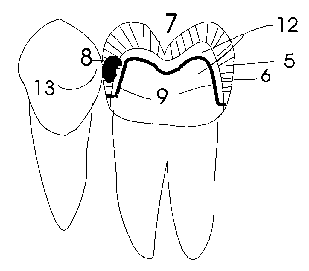
[0057]FIG. 2. demonstrates the anatomy and position of most interproximal decay as it relates to the anatomy of a tooth. 8 refers to caries penetrating enamel 5 and dentin 12, starting gingival to the contact area 13, extending occlusally 7 and axially towards 9. 9 refers to the slightly inclined axial wall of the preparation which idea...


PUM


Abstract

A device for creating interproximal contacts of restorations placed between posterior and anterior teeth comprising a single or plurality of dental inserts which is sized and dimensioned and can be inserted into unset restorative material and compacted so as to exert lateral forces in the interproximal areas of tooth preparations thereby creating tight anatomical and functional interproximal contacts. A method of use of said dental inserts is also described.

Description

[0001] The present application claims the benefit of U.S. Provisional Patent Application Ser. No. 60 / 570,866 entitled “Dental Insert and Method of tooth Restoration” filed May 14, 2004. The contents of this application is incorporated herein by reference.FIELD OF INVENTION [0002] A dental insert is described which is hard and compressible and is curved or rounded of various shapes and sizes and which can be inserted into unset restorative material and compacted so as to exert lateral forces in interproximal areas of tooth preparations for posterior and anterior restorations thereby creating tight anatomical and functional interproximal contacts. A method of use of said dental inserts is also described. BACKGROUND OF THE INVENTION [0003] Amalgam restorations are dense and compactable and an operator could easily condense amalgam into a proximal cavity thereby creating a well defined and strong contact area with a proximal tooth. Composite resins in general are not nearly as dense or ...

Claims


Application Information

Patent Timeline
Patent Type & Authority Applications(United States)
IPC IPC(8): A61C5/04A61C5/12
CPCA61C5/125A61C5/04A61C5/85
Inventor COOPERSMITH, ALLAN
Owner COOPERSMITH ALLAN
Why Eureka
Try Eureka