

Positioning apparatus, exposure apparatus, and device manufacturing method
a technology of exposure apparatus and positioning position, which is applied in the direction of photomechanical apparatus, instruments, printing, etc., can solve the problems of reducing the positioning accuracy affecting the driving and positioning of the other stage, and prolonging the settling time during positioning, so as to achieve high accuracy and simplify the apparatus structure
- Summary
- Abstract
- Description
- Claims
- Application Information
AI Technical Summary
Benefits of technology
Problems solved by technology
Method used
Image

Examples
first embodiment
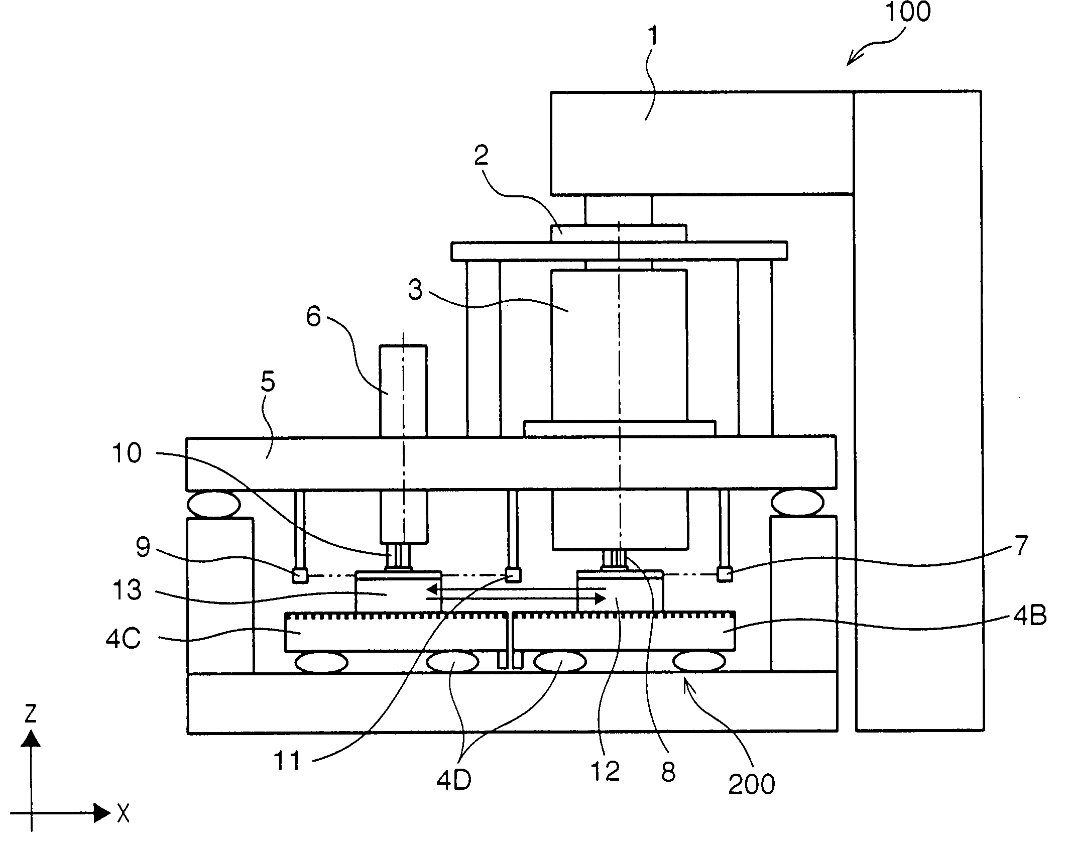
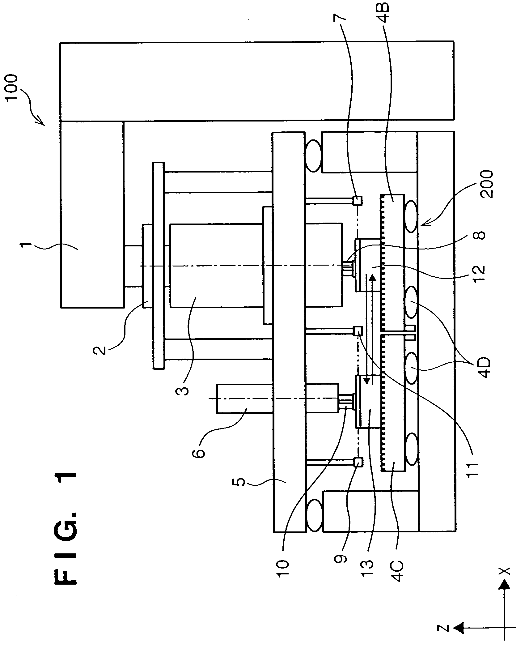
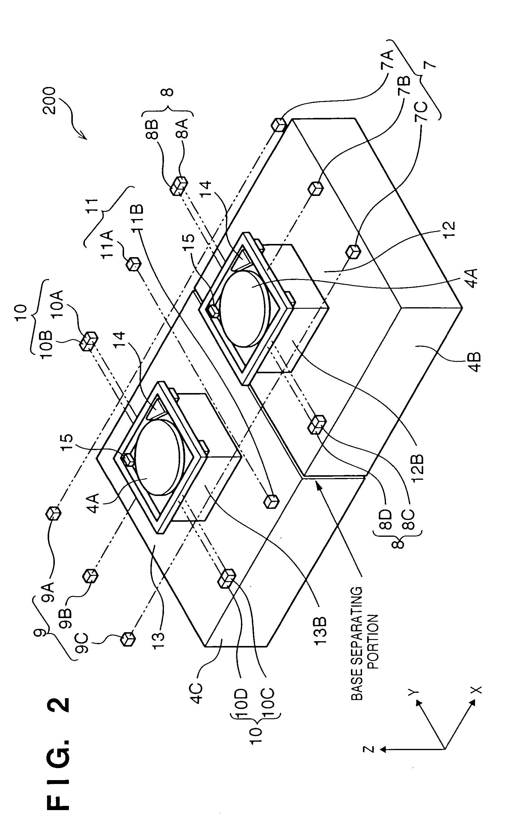
[0043]FIG. 1 is a side view showing the schematic structure of an exposure apparatus according to a preferred embodiment of the present invention, and FIG. 2 is a perspective view showing the schematic structure of a positioning apparatus according to the preferred embodiment of the present invention which is to be built into the exposure apparatus shown in FIG. 1. A positioning apparatus 200 has first and second stages 12 and 13 which respectively hold and move wafers (substrates). An exposure apparatus 100 into which the positioning apparatus 200 is built has an exposure process area 96 (see FIG. 5) where an exposure process (a process of forming a latent pattern on a photosensitive agent coated on a wafer) is performed, an alignment process area 95 (see FIG. 5) where an alignment process (a process of detecting a mark position or the like on the wafer for alignment) is performed, and a swap area 16 (see FIG. 5) where a stage present in the exposure process area and a stage presen...
second embodiment
[0085] The second embodiment provides a modification of the first embodiment. Matters that are not particularly referred to herein can follow the first embodiment. FIGS. 13A and 13B are enlarged views of the portion C of FIG. 3.
[0086] A stage base which supports first and second stages 12 and 13 is separated into first and second stage bases 4B and 4C, in the same manner as in the first embodiment. When the first and second stages 12 and 13 are to be driven independently of each other (that is, when an exposure process and alignment process are to be performed simultaneously), as shown in FIG. 13A, the first and second stage bases 4B and 4C are arranged sufficiently separate from each other so they are not brought into contact with each other by reaction forces which are generated when the sliders on which the stages are mounted are driven. When the positions of the first and second stages 12 and 13 are to be swapped, the first and second stage bases 4B and 4C are moved close to ea...
third embodiment
[0089] The third embodiment provides a modification of the first or second embodiment. Matters that are not particularly referred to herein can follow the first or second embodiment. FIG. 14 is an enlarged view of the portion C of FIG. 3.
[0090] According to this embodiment, chamfered portions 4E are formed on those ends of the guide surfaces of first and second stage bases 4B and 4C which correspond to the opposing portions of the first and second stage bases 4B and 4C. The chamfered portions 4E may be flat surfaces as shown in FIG. 14, or may be smooth surfaces such as curved structures. When the chamfered portions 4E are respectively formed on the first and second stage bases 4B and 4C, even if a positioning error exists between the first and second stage bases 4B and 4C, or the height difference between the first and second stage bases 4B and 4C exceeds the levitating amount (the gap between the stage bases and sliders) of the sliders produced by the air bearing, as in a case wh...
PUM
 Abstract
Description
Claims
Application Information