Method and device for head tracking

a head tracking and head tracking technology, applied in the field of head tracking methods and devices, can solve the problems of unfavorable fact that three sensors are needed and complicated configuration, and achieve the effect of judiciousness even more accurately

Inactive Publication Date: 2005-11-17
SONY CORP
View PDF9 Cites 147 Cited by
  • Summary
  • Abstract
  • Description
  • Claims
  • Application Information

AI Technical Summary

Benefits of technology

[0019] A sixth aspect of the present invention is the head-tracking device according to the fourth aspect of the present invention, in which the calculation means performs correction of the yaw angle judged from the output of the gyro sensor using the pitch angle and the roll angle calculated. Accordingly, the yaw angle can be judged even more accurately.

Problems solved by technology

However, a conventional head mounted display requires three acceleration sensors, which separately detect the acceleration of each of the three orthogonal axes, as a sensor unit which detects the movement of the head, resulting in a problem of making the configuration complicated.
In particular, a head mounted display is a piece of equipment worn on a user's head, so that it is preferable to be compact and light and the fact that three sensors are necessary has been unfavorable.

Method used


Image

  • Method and device for head tracking
  • Method and device for head tracking
  • Method and device for head tracking

Examples


Embodiment Construction

[0031] Hereinafter, an embodiment of the present invention will be explained referring to FIGS. 1 to 10.

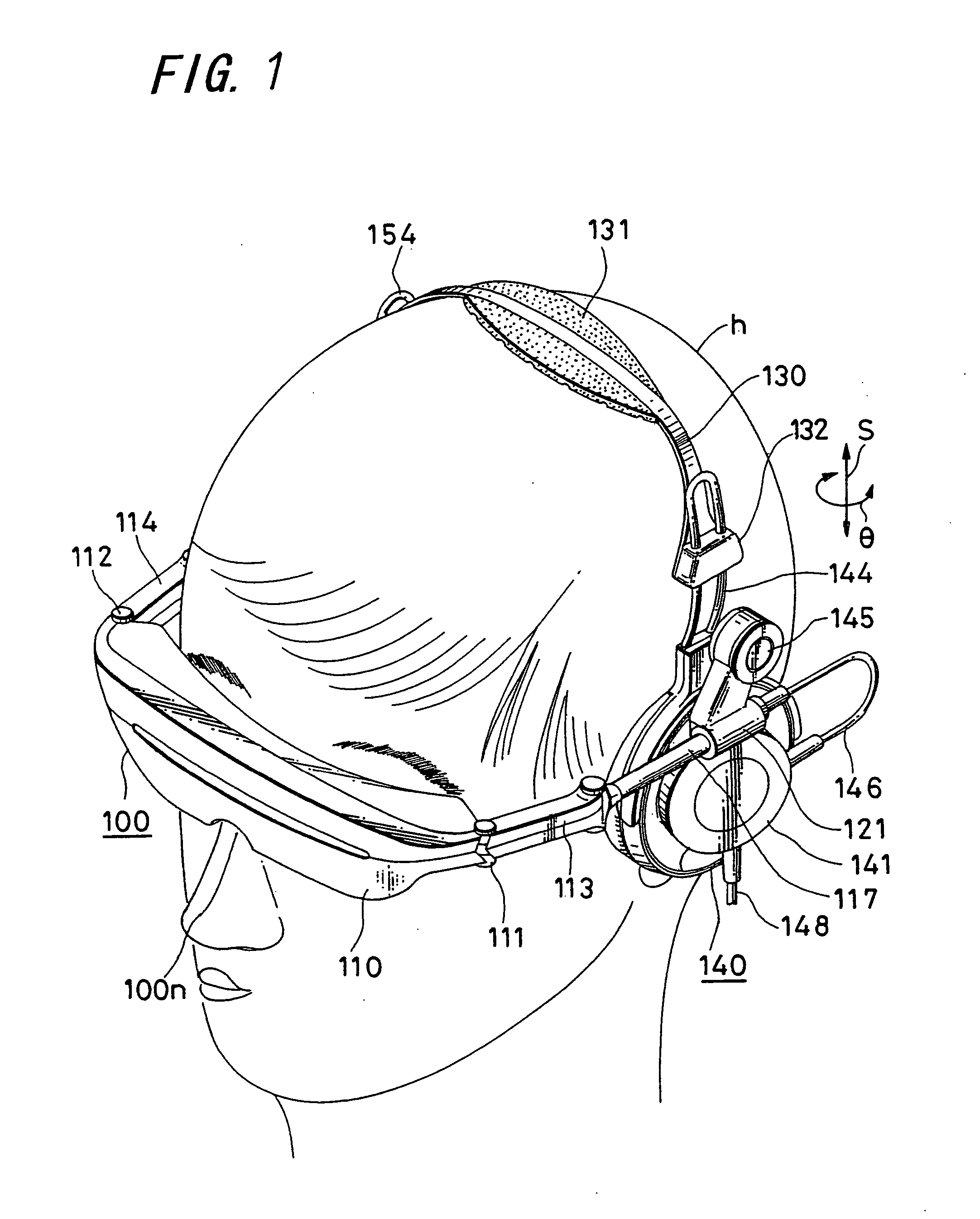
[0032]FIG. 1 is a view showing an example in which a head mounted display of this embodiment is being worn. A head mounted display 100 of this embodiment is shaped like headphones worn above the left and right auricles of the head h of a user; and to the headphones-like shape, a video display unit is attached. FIG. 1 shows a state in which a video display unit 110 is positioned in front of the user's eyes to watch and listen to video and audio. This head mounted display 100 is connected to an video signal source not shown in the figure through a cable 148, and video supplied from the video signal source is displayed in the video display unit 110 and audio supplied is output from driver units worn on the left and right auricles. In this embodiment, sensors which detect the direction a wearer faces are incorporated in the head mounted display 100, and a video corresponding to the d...


PUM


Abstract

When the three-dimensional direction the head faces is detected by three axes, that is, a yaw angle that is an angle turning around an erect axis erected on the horizontal surface of the head, and a pitch angle and a roll angle that are angles formed by the above erect axis and two axes perpendicular thereto, a gyro sensor 11 which detects the yaw angle from the integral value of the acceleration, a tilt sensor 12 which detects the inclination of a plane that intersects the direction of the erect axis at right angles, and calculation element 14 which calculates the pitch angle and the roll angle from the output of a tilt sensor are provided, so that the direction that the head faces can be detected with a simple detecting structure including the two sensors, in a head mounted display or the like.

Description

TECHNICAL FIELD [0001] The present invention relates to a head-tracking method and device which detect the direction that the head faces in a head mounted display or the like. BACKGROUND ART [0002] In recent years, various kinds of method and device which detect by a sensor the three-dimensional direction that the head of a person faces and which display video in the direction detected on a head mounted display (HMD) worn on the head have been put into practical use to obtain what is called “virtual reality”. [0003]FIG. 11 is a diagram showing an example of a configuration of a conventional head mounted display. In this example, the conventional head mounted display includes a sensor unit 70 which detects the movement of the head, a head mounted display unit 80 which is worn on the head, and a host unit 90 which supplies video signals to the video display unit 80. The sensor unit 70 includes three sensors 71, 72 and 73 which detect the movement of the head of a person in a three-dim...

Claims


Application Information

Patent Timeline
Patent Type & Authority Applications(United States)
IPC IPC(8): G02B27/00G01C19/00G02B27/01G02B27/02G06F3/00G06F3/01G06F3/033H04N5/64
CPCG02B27/0093G02B27/017G06F3/0346G02B2027/0198G06F3/012G02B2027/0187G01C19/00G02B27/02H04N5/64
Inventor KURATA, MASATOMO
Owner SONY CORP
Why Eureka
Try Eureka