Variable valve timing control system of internal combustion engine

a timing control system and internal combustion engine technology, applied in the direction of valve details, valve arrangements, valve drives, etc., can solve the problems of unfavorable energy loss, increased torque capacity, undesirable load of pulse pressure, etc., to increase the tendency of pulse pressure, increase the torque capacity, and large system size

Inactive Publication Date: 2005-11-24
HITACHI LTD
View PDF12 Cites 44 Cited by
  • Summary
  • Abstract
  • Description
  • Claims
  • Application Information

AI Technical Summary

Benefits of technology

[0003] However, in the system disclosed in JP2001-271616, the phase-advance hydraulic chamber is connected directly to a first port of two ports of the reversible pump via a first fluid line. In a similar manner, the phase-retard hydraulic chamber is connected directly to the second port of the reversible pump via a second fluid line. As is generally known, a comparatively large magnitude of alternating torque is exerted on the camshaft owing to a spring force of a valve spring for each engine valve and a reaction force resulting from each valve lifting during operation of the engine. Due to the alternating torque, a pulse pressure is applied to the working fluid in each of the phase-advance and phase-retard hydraulic chambers. There is an increased tendency for the pulse pressure, arising from

Problems solved by technology

The pulsating pressure serves as an undesirable load (in other words, undesirable energy loss) carried on the motor shaft of the electric motor of the reversible pump.
Such an und

Method used


Image

  • Variable valve timing control system of internal combustion engine
  • Variable valve timing control system of internal combustion engine
  • Variable valve timing control system of internal combustion engine

Examples


Embodiment Construction

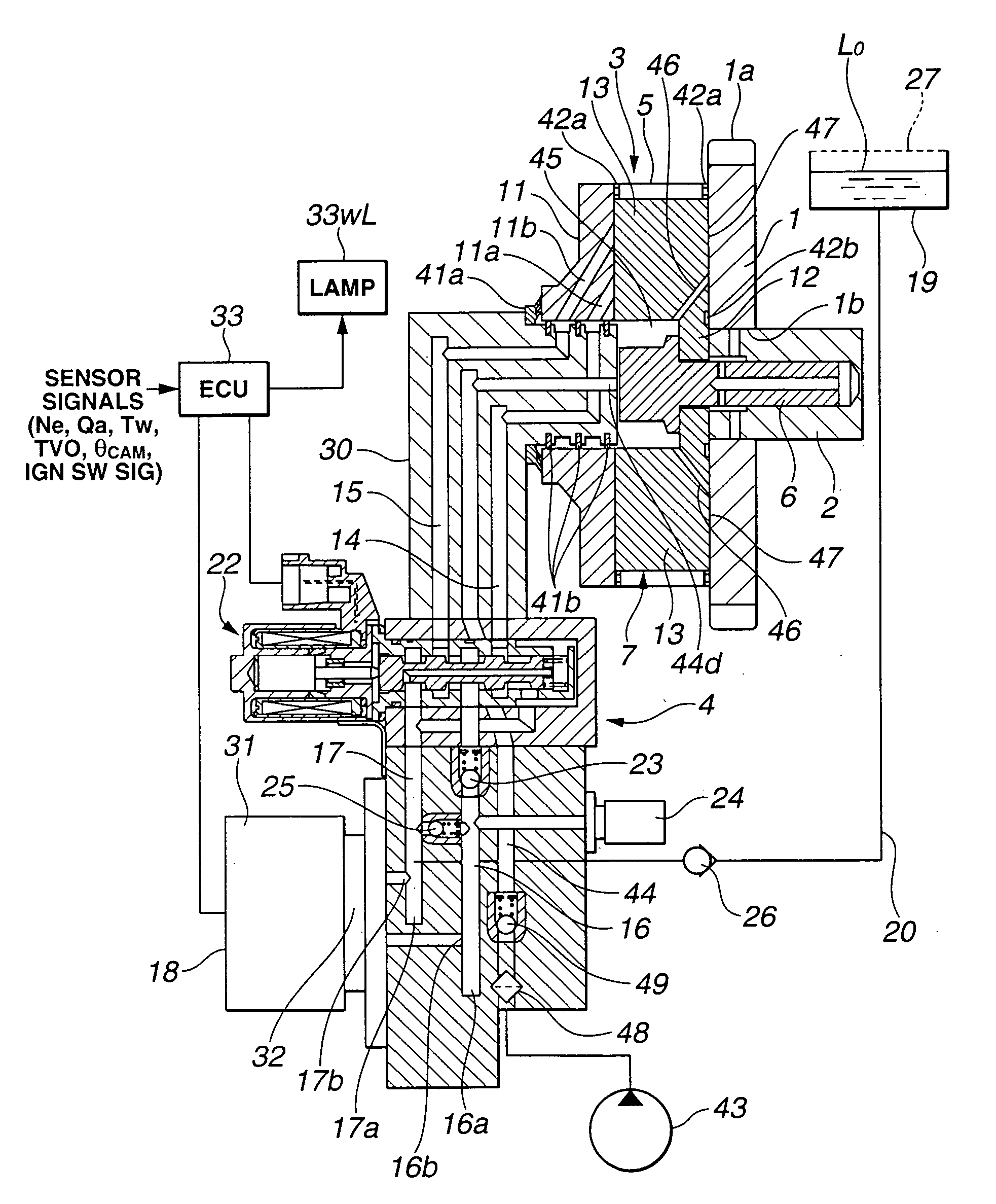
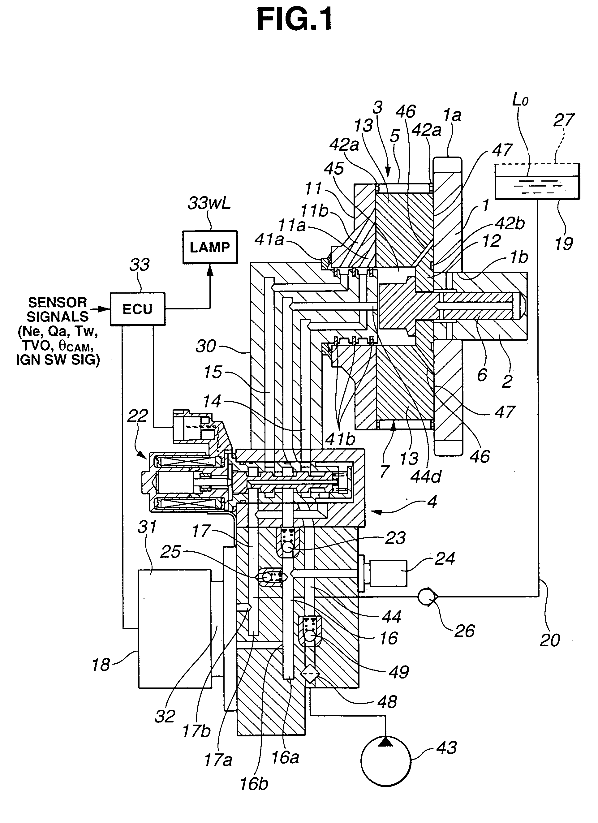
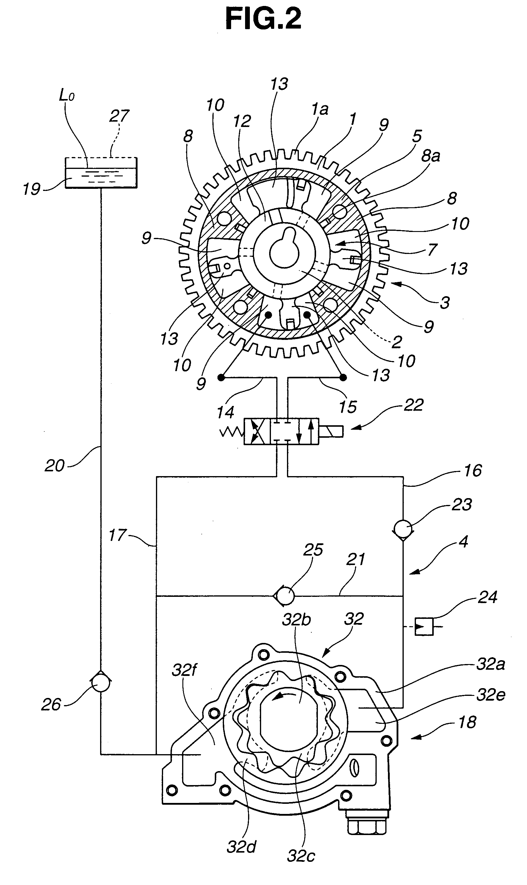
[0021] Referring now to the drawings, particularly to FIGS. 1 and 2, the hydraulically-operated phase converter equipped variable valve timing control system of the embodiment is exemplified in an automotive vehicle with a vane-type timing variator.

[0022] As shown in FIG. 1, the variable valve timing control system of the embodiment is comprised of a disc-shaped sprocket 1, a camshaft 2, a phase converter 3, and a hydraulic circuit 4. Sprocket 1 serves as a rotary member, which is driven in synchronism with rotation of an engine crankshaft (not shown) via a timing chain. Camshaft 2 is provided to operate engine valves such that relative rotation between sprocket 1 and camshaft 2 is permitted. Phase converter 3 is disposed between sprocket 1 and camshaft 2 for converting or changing an angular phase of camshaft 2 relative to sprocket 1. Hydraulic circuit 4 is connected to phase converter 3 to hydraulically operate phase converter 3.

[0023] Sprocket 1 has an outer toothed portion 1a ...


PUM


Abstract

A variable valve timing control system of an internal combustion engine includes a hydraulically-operated phase converter disposed between a sprocket and a camshaft, and having a phase-advance hydraulic chamber and a phase-retard hydraulic chamber for changing an angular phase of the camshaft relative to the sprocket. An electric pump is provided to supply working fluid selectively to one of the hydraulic chambers via a directional control valve. Also provided is a check valve disposed in a discharge line of the pump for permitting flow in a direction that the working fluid flows from the pump to the directional control valve and preventing any flow in the opposite direction, so as to prevent a pulse pressure arising from alternating torque exerted on the camshaft from being transmitted from either one of the hydraulic chambers via the discharge line to a discharge port of the pump.

Description

TECHNICAL FIELD [0001] The present invention relates to a variable valve timing control system employing a hydraulically-operated phase converter capable of varying a relative phase of a camshaft to a crankshaft of an internal combustion engine by supplying working fluid (hydraulic pressure) selectively to either one of a phase-advance hydraulic chamber and a phase-retard hydraulic chamber, for variably adjusting an open-and-closure timing of an engine valve depending on an engine operating condition. BACKGROUND ART [0002] In recent years, there have been proposed and developed various variable valve timing control systems each employing a phase converter, such as a hydraulically-operated vane-type timing variator, a hydraulically-operated helical-gear-type timing variator, and the like. A hydraulically-operated vane-type timing variator has been disclosed in Japanese Patent Provisional Publication No. 2001-271616 (hereinafter is referred to as “JP2001-271616”), corresponding to Ger...

Claims


Application Information

Patent Timeline
IPC IPC(8): F01L1/34F01L1/344
CPCF01L1/022F01L1/3442F01L2001/34423F01L2001/34426F01L2800/03F01L2001/34433F01L2001/34436F01L2001/34446F01L2800/01F01L2001/3443
Inventor SAWADA, TAKANORI
Owner HITACHI LTD
Why Eureka
Try Eureka