Manufacturing method for a soft magnetic material, a soft magnetic material, a manufacturing method for a powder metallurgy soft magnetic material, and a powder metallurgy soft magnetic material

Inactive Publication Date: 2005-11-24
SUMITOMO ELECTRIC IND LTD
View PDF8 Cites 23 Cited by
  • Summary
  • Abstract
  • Description
  • Claims
  • Application Information

AI Technical Summary

Benefits of technology

[0007] Furthermore, in order to adequately reduce the distortions present in the interior of the dust core, the temperature of heat treatment could be raised. However, because the phosphate compound coating the atomized iron powder has poor heat resistance, it can deteriorate if the temperature during heat treatment is set too high. Because of this, the eddy current loss between particles of phosphate-coated atomized ir

Problems solved by technology

In the interior of the dust core created in this manner, if there are numerous distortions (point defects, dislocations, crystal grain boundaries), these distortions interfere with the magnetic domain wall displacement (magnetic flux changes) and causes reduced magnetic permeability of the dust core.
With the dust core disclosed in Japanese Laid-Open

Method used


Image

  • Manufacturing method for a soft magnetic material, a soft magnetic material, a manufacturing method for a powder metallurgy soft magnetic material, and a powder metallurgy soft magnetic material
  • Manufacturing method for a soft magnetic material, a soft magnetic material, a manufacturing method for a powder metallurgy soft magnetic material, and a powder metallurgy soft magnetic material
  • Manufacturing method for a soft magnetic material, a soft magnetic material, a manufacturing method for a powder metallurgy soft magnetic material, and a powder metallurgy soft magnetic material

Examples


embodiment 1

(Embodiment 1)

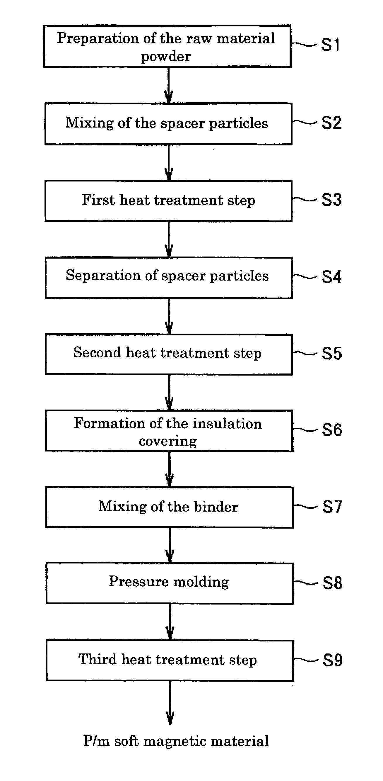
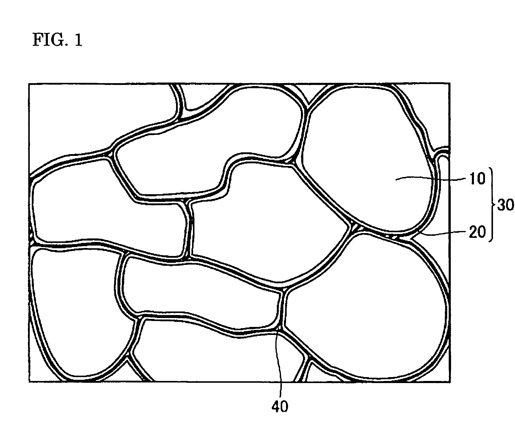
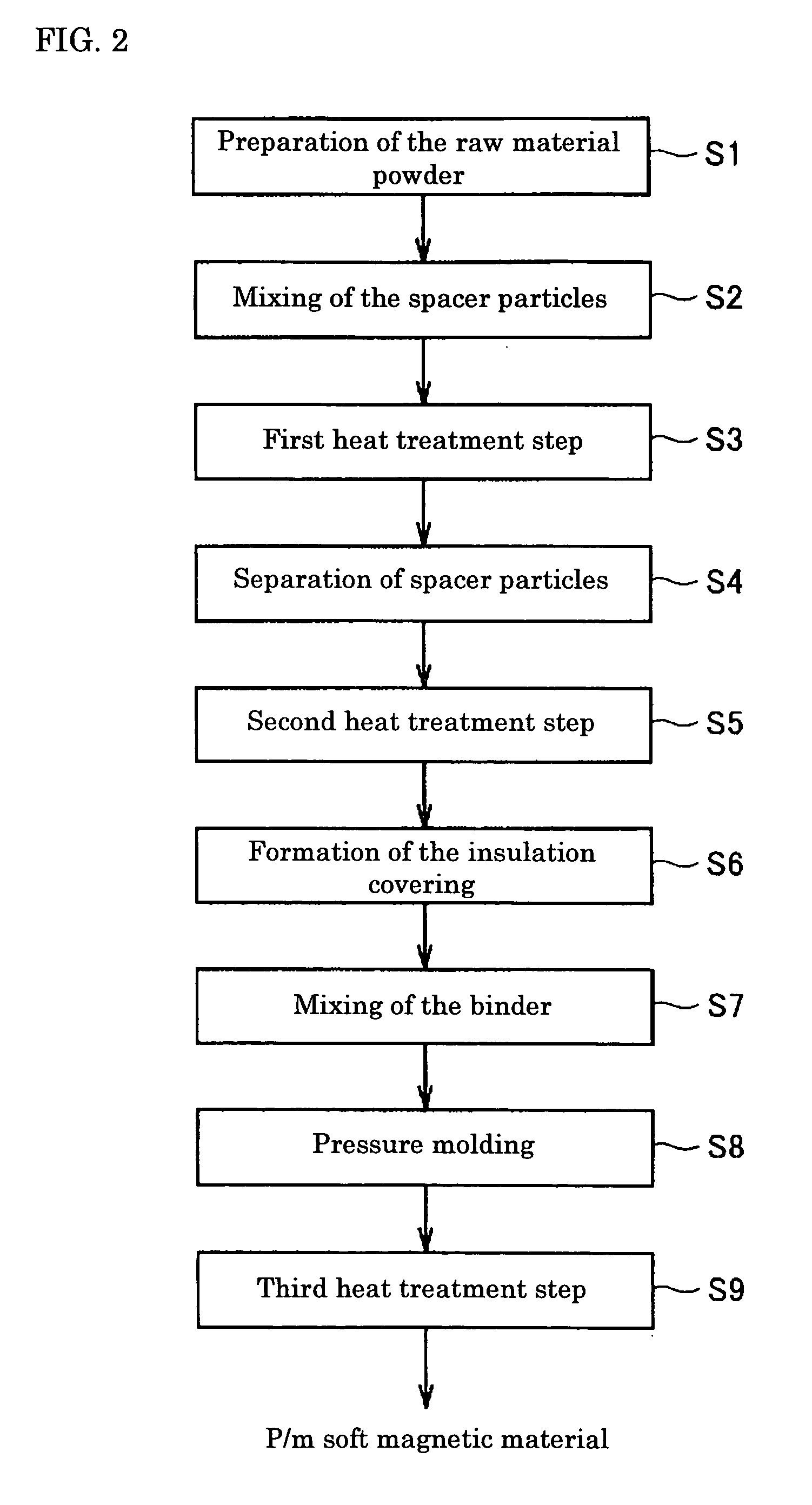
[0093] In the present embodiments, the P / M soft magnetic material is created in accordance with the manufacturing method of FIG. 1 described in the Implementation mode 1. The effect of conducting the first heat treatment step and the effect of mixing spacer particles 7 were studied. Stated more concretely, samples A1-A6, samples B1-B6, and sample Z were each created according to the following manufacturing methods, and their coercive forces, hysteresis loss, and iron loss were measured.

[0094] (Samples A1-A6):

[0095] For metal magnetic particles 10, atomized pure iron powder (product name ABC100.30) produced by Hoganas was prepared, and metal magnetic particles 10 of particle size 75 micrometers to 250 micrometers were separated. Next, 500 g of metal magnetic particles 10 and 400 g of spacer particles 7 were mixed. For spacer particle 7, ZrO2 of particle size 200 micrometers was used. Next, under differing temperature conditions ranging from 950 degrees C. to 1450 degr...

embodiment 2

(Embodiment 2)

[0103] In the present embodiment, the P / M soft magnetic material of FIG. 1 was created according to the manufacturing method described in Implementation mode 2. The effect of conducting the first heat treatment step and the effect of conducting the first heat treatment step while stirring metal magnetic particles 10 were studied. Stated more concretely, samples C1-C6, samples B1-B6, and sample Z were each produced according to the following manufacturing method. The coercive force, hysteresis loss, and iron loss were measured.

[0104] (Samples C1-C6):

[0105] The first heat treatment step was conducted without mixing spacer particles. As shown in FIG. 5, the first heat treatment step was conducted while stirring metal magnetic particles 10. Otherwise, the manufacturing method was the same as the manufacturing method for samples A1-A6, and its description is omitted.

[0106] (Samples B1-B6):

[0107] The first heat treatment step was conducted without stirring metal magnetic...


PUM

PropertyMeasurementUnit
Temperatureaaaaaaaaaa

Abstract

The object of the present invention is to provide a method for manufacturing a soft magnetic material, a soft magnetic material, a method for manufacturing a P/M soft magnetic material, and a P/M soft magnetic material which achieve the desired magnetic properties.
In the method for manufacturing the soft magnetic material of the present invention, there is a first heat treatment step (step S3) in which a metal magnetic particle 10, which has iron as its main component, is heat treated to a temperature of 900 degrees C. or greater and less than the melting point of metal magnetic particle 10. After the first heat treatment step (step S3), there is a step for forming a plurality of composite magnetic particles 30 which are metal magnetic particles 10 surrounded by an insulation covering 20 (step S6).

Description

BACKGROUND OF THE INVENTION [0001] 1. Field of the Invention [0002] The present invention relates to a manufacturing method for a soft magnetic material, a soft magnetic material, a manufacturing method for a powder metallurgy (P / M) soft magnetic material, and a P / M soft magnetic material. More specifically, the present invention relates to a manufacturing method for a soft magnetic material, a soft magnetic material, a manufacturing method for a P / M soft magnetic material, and a P / M soft magnetic material which use a composite magnetic particle constructed from a metal magnetic particle and an insulating covering which surrounds this metal magnetic particle. [0003] 2. Description of the Background Art [0004] In the prior art, with electronic components such as cores of motors and cores of transformers and the like, there have been attempts to increase density and decrease size, and there is a desire for a more precise control using less power. Because of this, there have been advan...

Claims


Application Information

Patent Timeline
IPC IPC(8): B22F1/00B22F1/02B22F3/00B22F3/02B22F3/24H01F1/24H01F1/33H01F41/02
CPCH01F41/0246H01F1/24
Inventor MAEDA, TORUIGARASHI, NAOTOTOYODA, HARUHISAMIMURA, KOJI
Owner SUMITOMO ELECTRIC IND LTD
Why Eureka
Try Eureka