Method of driving organic light emitting diode

Inactive Publication Date: 2005-11-24
RITDISPLAY
View PDF13 Cites 29 Cited by
  • Summary
  • Abstract
  • Description
  • Claims
  • Application Information

AI Technical Summary

Benefits of technology

[0010] The present invention provides a method for driving an organic light emitting diode that uses precharge mechanism to precharge an anod

Problems solved by technology

However, due to the intrinsic physical property of the organic light emitting diode, a parasitic capacitance exists.
When the voltage across the cathode and anode of the organic light emitting diode cannot instantly reaches an appropriate value, the required luminance of the organic light emitting diode cannot be obtained.
Further, as shown in FIG. 3, the conventional driving system of the organic light emitting diode suffers the problem of excessively long rising time for conducting the diode due to the parasitic capacitance of the organic light emitting diode panel.
At the ins

Method used


Image

  • Method of driving organic light emitting diode
  • Method of driving organic light emitting diode
  • Method of driving organic light emitting diode

Examples


first embodiment

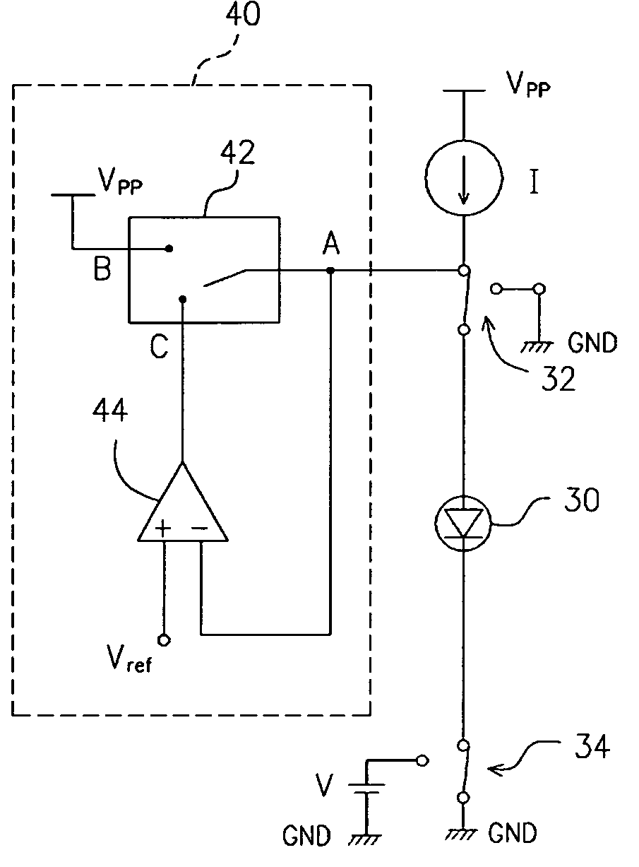
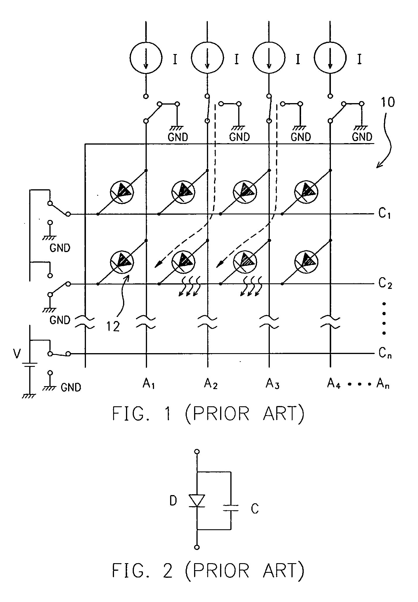
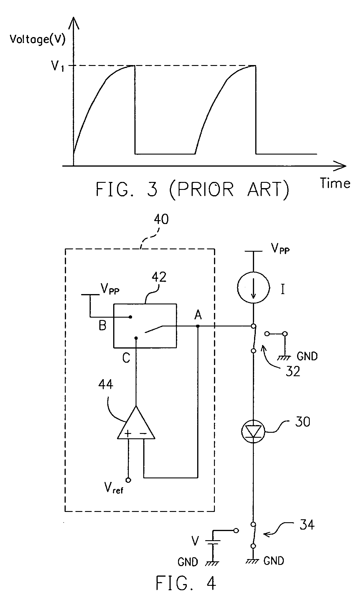
[0032] Referring to FIG. 4, a passive driving circuit of an organic light emitting diode of a first embodiment according to the present invention is illustrated. For the convenience of description, only one light emitting diode in a whole organic light emitting diode array is described. People of ordinary skill in the art can integrate the whole organic light emitting diode according thereto.

[0033] In FIG. 4, a precharge circuit 40 is electrically connected to an anode of an organic light emitting diode 30. The anode of the organic light emitting diode 30 is connected to a constant current source I and a voltage source Vpp via a switching device 32, while the cathode thereof is connected to a voltage V or a grounded GND via a switching device 34 for providing reverse bias. To light up the organic light emitting diode 30, the switching device 32 is closed to provide the constant current I to the organic light emitting diode 30, while the switching device 34 is connected to the groun...

second embodiment

[0041] Referring to FIG. 6A, a circuit diagram of a driving circuit of an organic light emitting diode is illustrated. For the convenience of description, only the relationship between one light emitting diode and the precharge circuit is illustrated. However, according the embodiment, people of ordinary skill in the art can integrate the whole organic light emitting diode array.

[0042] The second embodiment differs from the first embodiment by the design of the reference voltage Vref. The function and connection of comparator 54 and the switching device 52 are the same as the comparator 44 and the switching device 42 described in the first embodiment, so that the description is not repeated.

[0043] In the first embodiment, the reference voltage Vref is adjusted and varied ref externally. That is, the reference voltage Vref cannot be adjusted dynamically. Under such circumstance, when the brightness of the organic light emitting diode 30 is changed, or the I-V-B characteristic curve...

third embodiment

[0049] Referring to FIG. 7A, a circuit for driving the organic light emitting diode according to a third embodiment of the present invention is illustrated. For the convenience of description, only the relationship between one light emitting diode and the precharge circuit is illustrated. However, according the embodiment, people of ordinary skill in the art can integrate the whole organic light emitting diode array.

[0050] In the first and second embodiments, a constant precharge voltage is used to adjust the precharging time. That is, in FIGS. 6A and 7A, the precharge voltage Vpp is constant. However, with such structure, the actual precharging time cannot be controlled. Instead, a feedback mechanism has to be used for automatic control. Therefore, when the uniformity of the output of anode voltage is highly demanded, particularly while using pulse-width modulation method for gray scale, the charging time is preferably shorter. Thus, in the third embodiment, the precharging time i...


PUM


Abstract

A method of driving an organic light emitting diode using an applied voltage to increase the voltage of the anode is provided. The voltage of the anode is detected and compared to a reference voltage. When the voltage of the anode is lower than the reference voltage, a voltage source is applied to precharge the anode of the organic light emitting diode. When the voltage of the anode reaches the reference voltage, the precharge process is stopped. Alternatively, the reference voltage can be dynamically obtained using a sample/hold circuit to dynamically perform sampling on the output voltage of a constant current source.

Description

BACKGROUND OF INVENTION [0001] 1. Field of the Invention [0002] The invention relates in general to a method of driving an organic light emitting diode, and more particularly, to a passive driving method of an organic light emitting diode. [0003] 2. Related Art of the Invention [0004] To comply with versatility of modern information apparatus, the flat panel that replaces the cathode ray tube (CRT) display due to the trends of being thin, light, short, small and power saving is strongly demanded. Currently, the available flat panel display techniques include plasma display, liquid crystal display (LCD), electroluminescent display, light emitting diode (LED), field emission display, electrochromic display, and organic light emitting diode (OLED) display. [0005] Two types of luminescent materials, including small molecular material and polymer material, have been employed in the organic light emitting diode display. Having the characteristics of: (1) viewing angle independence; (2) lo...

Claims


Application Information

Patent Timeline
IPC IPC(8): G09G3/32
CPCG09G3/3216G09G2320/0252G09G2310/0248
Inventor WU, JIE-FARN
Owner RITDISPLAY
Why Eureka
Try Eureka