Image display

Inactive Publication Date: 2005-11-24
BRIDGESTONE CORP
View PDF5 Cites 116 Cited by
  • Summary
  • Abstract
  • Description
  • Claims
  • Application Information

AI Technical Summary

Benefits of technology

[0006] Objects of first to third aspects of the invention are to eliminate the drawbacks mentioned above and to provide an ima

Problems solved by technology

However, in the electrophoresis method, there is a problem that a response speed is slow by the reason of viscosity resistance because the particles migrate among the electrophoresis solution.
Further, there is a problem of lacking imaging repetition stability, because particles with high specific gravity of titanium oxide is scattered within solution of low specific gravity, it is easy to subside, difficult to maintain a stability of dispersion state.
Even i

Method used


Image

  • Image display
  • Image display
  • Image display

Examples


Example

Example 1

First Aspect of the Invention

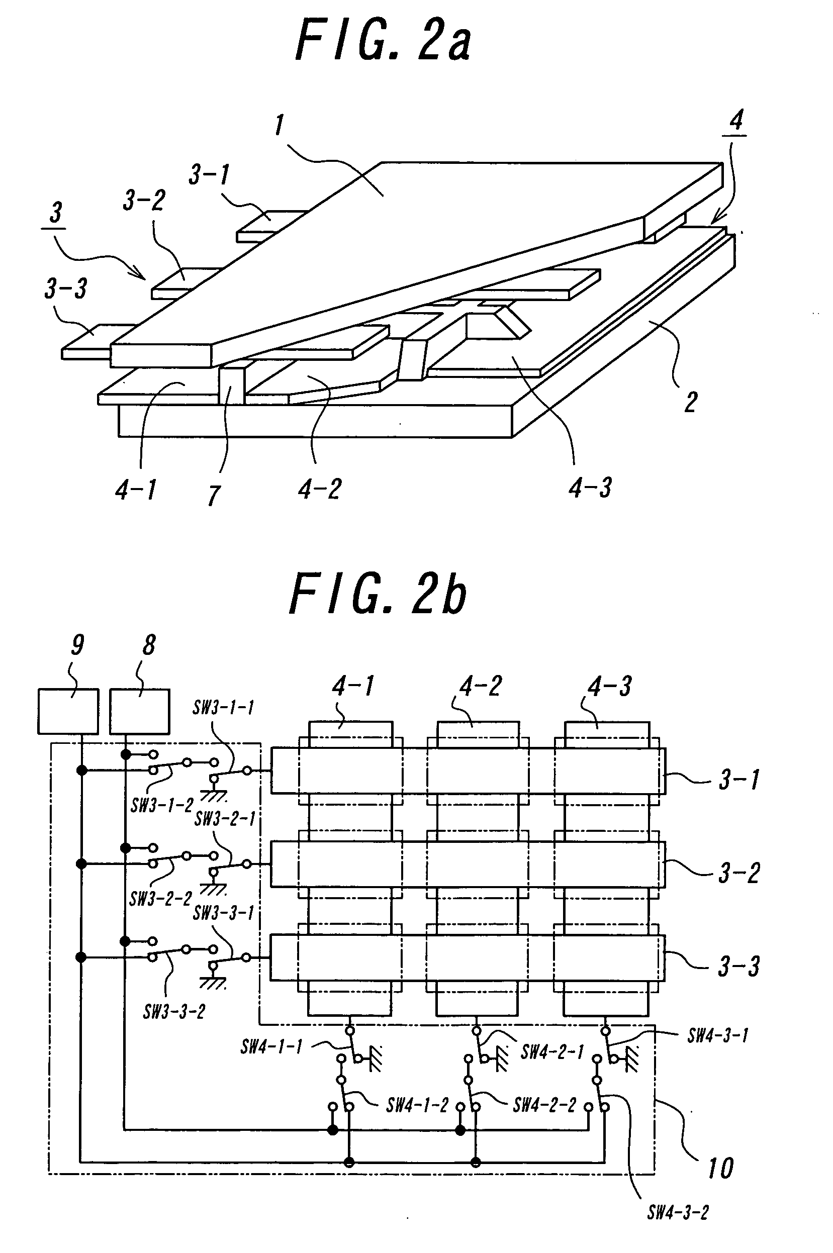
[0084] The image display panel shown in FIG. 2 was assembled. A glass substrate was employed as the transparent substrate 1, an epoxy substrate was employed as the opposed substrate 2, an ITO electrode was employed as the display electrode 3 and a copper electrode was employed as the opposed electrode 4. On the surfaces of respective electrodes 3 and 4, an insulating silicon resin was coated with the thickness about 3 μm for the purpose of preventing an adhesion and a charge leakage. Black toners (spherical toners with average particle diameter of 8 μm, surface charge density of −50 μC / m2, the surface potential of 450 V at 0.3 second after the foregoing surface potential measurement) for electro-photography were employed as the negatively chargeable particles 5. Polymerized particles of styrene-acrylic resin (spherical toners with average particle diameter of 8 μm, surface charge density of +45 μC / m2, the surface potential of 500 V at 0.3 seco...

Example

Example 2

Second Aspect of the Invention

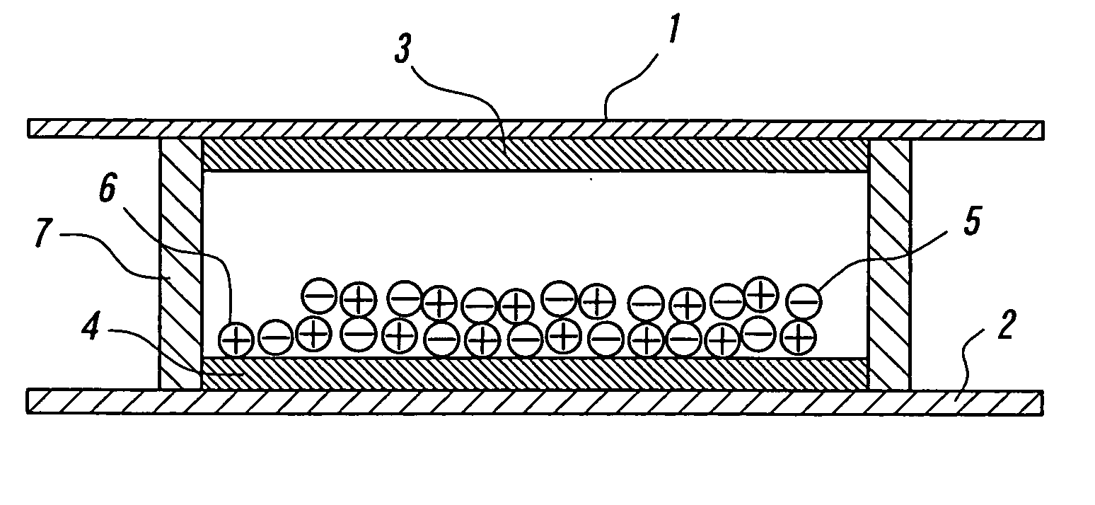
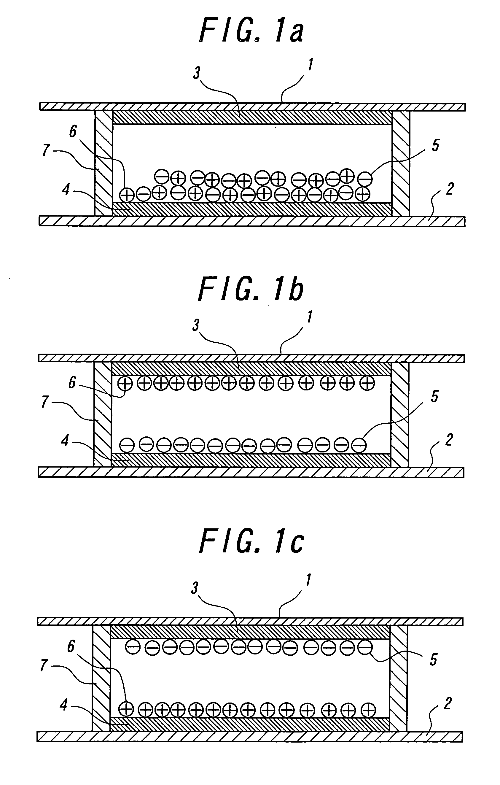
[0086] The image display panel shown in FIG. 1a was assembled. A glass substrate was employed as the transparent substrate 1, an epoxy substrate was employed as the opposed substrate 2, an ITO electrode was employed as the display electrode 3 and a copper electrode was employed as the opposed electrode 4. On the surfaces of respective electrodes 3 and 4, an insulating silicon resin was coated with the thickness about 1 μm for the purpose of preventing an adhesion and a charge leakage. Black toners (spherical toners 2 with average particle diameter of 8 μm, surface charge density of −50 μC / m2, the surface potential of 450 V at 0.3 second after the foregoing surface potential measurement) for electro-photography were employed as the negatively chargeable particles 5. Polymerized particles of styrene-acrylic resin (spherical toners with average particle diameter of 8 μm, surface charge density of +45 μC / m2, the surface potential of 500 V at 0.3 ...

Example

Example 3

Third Aspect of the Invention

[0091] The image display panel shown in FIG. 4a was assembled. A glass substrate was employed as the transparent substrate 1, an epoxy substrate was employed as the opposed substrate 2, ITO electrodes were employed as the display electrodes 3-1, 3-2 and copper electrodes were employed as the opposed electrodes 4-1, 4-2. On the surfaces of respective electrodes 3-1, 3-2 and 4-1, 4-2, an insulating silicon resin was coated with the thickness about 3 μm for the purpose of preventing an adhesion and a charge leakage. Black toners (spherical toners with average particle diameter of 8 μm, surface charge density of −50° C. / m2, the surface potential of 450 V at 0.3 second after the foregoing surface potential measurement) for electro-photography were employed as the negatively chargeable particles 5. Polymerized particles of styrene-acrylic resin (spherical toners with average particle diameter of 8 μm, surface charge density of +45 μC / m2, the surface...


PUM


Abstract

An image display device has an image display panel, in which two or more groups of particles having different colors and different charge characteristics are sealed between two substrates, at least one of two substrates being transparent, and, in which the particles, to which an electrostatic field produced by a pair of electrodes provided on respective substrates is applied, are made to fly and move so as to display an image. (1) The image display panel has matrix electrodes composed of pairs of electrodes arranged in a matrix manner, a display drive is performed by applying a high potential VH or a low potential VL to respective electrodes constituting the matrix electrodes, and respective electrodes are connected to an intermediate potential V0 between the potentials VH and VL through a small impedance when the potential VH or VL is not applied to respective electrodes. (2) The image display device has an alternating voltage generating means for generating an alternating voltage with the frequency swept, and the alternating voltage from the alternating voltage generating means is applied between a pair of electrodes during the interval of displaying on the image display panel. (3) At least one of each pair of electrodes is composed of split electrodes, and a voltage is applied between the split electrode during the interval of displaying to fly and move the particles between the split electrodes.

Description

TECHNICAL FIELD [0001] The present invention relates to an image display device enables to repeatedly display or eliminate images accompanied by flight and movement of particles utilizing static charge. BACKGROUND ART [0002] As an image display device substitutable for liquid crystal display (LCD), image display devices with the use of technology such as an electro-phoresis method, an electro-chromic method, a thermal method, dichroic-particles-rotary method are proposed. [0003] As for these image display device, it is conceivable as inexpensive visual display device of the next generation from a merit having wide field of vision close to normal printed matter, having smaller consumption with LCD, spreading out to a display for portable device, and an electronic paper is expected. Recently, electrophoresis method is proposed that microencapsulate dispersion liquid made up with dispersion particles and coloration solution and dispose the liquid between faced substrates. [The Imaging ...

Claims


Application Information

Patent Timeline
IPC IPC(8): G09G3/34
CPCG09G2310/061G09G3/3433
Inventor NIHEI, NORIOTAKAGI, KOJIMURATA, KAZUYAYAKUSHIJI, GAKUKITANO, HAJIMEMASUDA, YOSHITOMOKAWAGOE, TAKAHIRO
Owner BRIDGESTONE CORP
Why Eureka
Try Eureka