Photothermal conversion spectroscopic analysis method and microchemical system for implementing the method

a technology of microchemical systems and spectroscopic analysis, applied in the direction of phase-affecting property measurements, instruments, measurement devices, etc., can solve the problems of vacuum required, sample broken or damaged, and what is actually used as such an optical microscope is limited to a laser fluorescent microscope, and achieves high sensitivity

Inactive Publication Date: 2005-11-24
NIPPON SHEET GLASS CO LTD
View PDF6 Cites 2 Cited by
  • Summary
  • Abstract
  • Description
  • Claims
  • Application Information

AI Technical Summary

Benefits of technology

[0024] With the arrangement of the first aspect of the present invention, the depth of the channel through which the sample to be detected flows should be not less than two times as large as the difference in focal position between the exciting light and the detecting light, whereby sufficient signal intensity can be obtained and hence the sample can be detected with high sensitivity. As a result, it is possible to carry out measurements on microscopic reactions that cannot be measured by the conventional methods.
[0026] According to the above construction, the light converging lens has chromatic aberration, so that it is possible to omit an optical system for adjusting the focal positions of the exciting light and the detecting light to thereby reduce the size of the microchemical system.
[0028] According to the above construction, the light converging lens is a rod lens and hence the light converging lens can be reduced in size and can be disposed closer to the channel. As a result, it is possible to further reduce the size of the microchemical system.
[0030] According to the above construction, an optical fiber is used as a light guiding path for guiding the exciting light and the detecting light to the light converging lens, so that it is not necessary to adjust the optical paths of the exciting light and the detecting light every time measurements are carried out, to thereby increase the working efficiency of a user. In addition, it is not necessary to provide a jig for adjusting the optical path to thereby reduce the size of the microchemical system. In the case where the exciting light and the detecting light are transmitted by a single optical fiber, the exciting light and the detecting light are always made coaxial, so that it is not necessary to provide a jig for adjusting the optical axis, whereby the microchemical system can be further reduced in size.
[0032] According to the above construction, a single-mode optical fiber is used and hence a thermal lens produced by the exciting light is small in size and have small aberration, which makes it possible to detect the sample with more precision.

Problems solved by technology

However, when a very small amount of substance or a very small substance is analyzed in a very small space by the conventional spectroscopic analysis method, there are problems that a vacuum is required as one of measurement conditions and that a sample is broken or damaged by the use of an electron beam or an ion beam.
What is actually used as such an optical microscope is limited to a laser fluorescent microscope.
However, in the conventional photothermal conversion spectroscopic analysis apparatus described above, the optical system including the light sources, the measurement section, and the detection section (photoelectric conversion section) has a complex construction, and hence such an apparatus has been large in size and has thus lacked portability.
Consequently, there is a problem that there are limitations with regard to the installation site and the operation of analysis and chemical reactions using the photothermal conversion spectroscopic analysis apparatus.
There is thus a problem that the position of the sample in which the thermal lens 131 is formed must be shifted from the focal position 133 of the detecting light every time measurement is carried out, as shown in FIGS. 4A and 4B, or else the detecting light must be slightly diverged or converged using a lens (not shown) before being introduced into the objective lens 130 so that the focal position 133 of the detecting light is shifted from the thermal lens 131 as shown in FIG. 5, which results in degraded work efficiency of the user.
Further, conventionally, in the photothermal conversion spectroscopic analysis, a method for detecting light with high sensitivity has not been proposed, which makes it impossible to design the measurement sensitivity, and hence a microchemical system of high performance cannot be manufactured with stability.

Method used


Image

  • Photothermal conversion spectroscopic analysis method and microchemical system for implementing the method
  • Photothermal conversion spectroscopic analysis method and microchemical system for implementing the method
  • Photothermal conversion spectroscopic analysis method and microchemical system for implementing the method

Examples


Embodiment Construction

[0044] The present invention will now be described with reference to the drawings showing a preferred embodiment thereof.

[0045] As a result of assiduous studies, the present inventors have found that in the photothermal conversion spectroscopic analysis method to be applied to a microchemical system, the intensity of detecting light depends on the relationship between the difference in focal position between exciting light and detecting light and the depth of a channel.

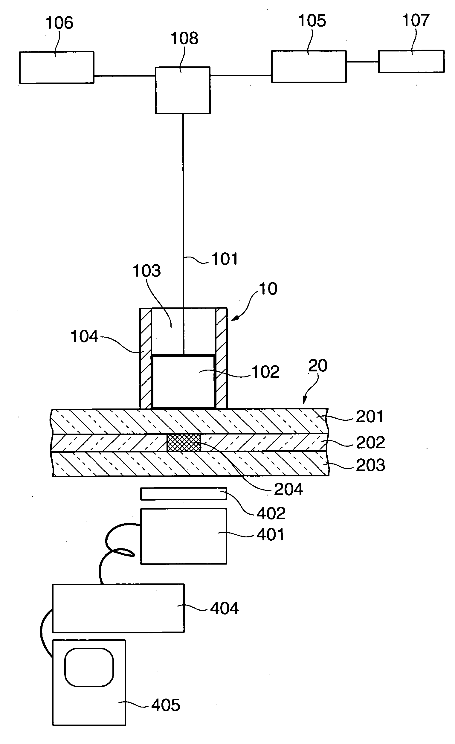
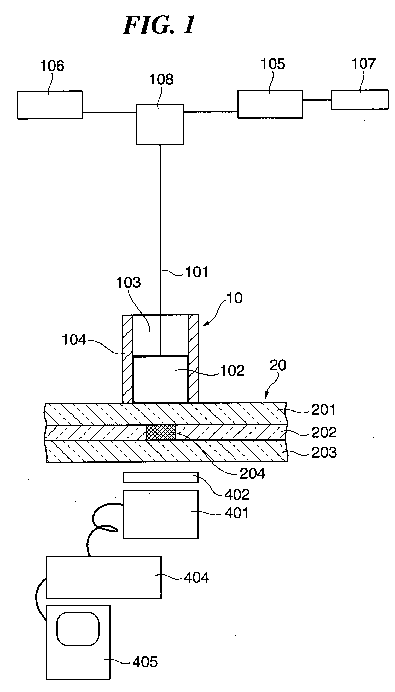
[0046]FIG. 1 is a schematic view showing the entire construction of a microchemical system according to an embodiment of the present invention. In FIG. 1, the microchemical system has an optical fiber 10 having a lens built therein (hereinafter referred to as the “optical fiber with lens 10”). The optical fiber with lens 10 has an optical fiber 101 inserted therein from a rear end thereof (the upper side as viewed in FIG. 1), for propagating exciting light and detecting light in a single mode. The end of the optical...


PUM

PropertyMeasurementUnit
depthaaaaaaaaaa
depthaaaaaaaaaa
refractive indexaaaaaaaaaa

Abstract

A photothermal conversion spectroscopic analysis method which is capable of performing analysis, measurement and detection with high sensitivity. A sample flows in a channel. A exciting light and a detecting light are exited. A gradient refractive index rod lens converges the exited light and forms a focal point at a position in or close to the channel. Intensity of the exited light and passing through the channel are detected. A depth of the channel is not less than two time as large as a difference in distance between focal positions of the exciting light and the detecting light.

Description

BACKGROUND OF THE INVENTION [0001] 1. Field of the Invention [0002] The present invention relates to a photothermal conversion spectroscopic analysis method and a microchemical system for implementing the method, that convergently irradiate exciting light and detecting light into a sample in a solution to form a thermal lens in the sample by the exciting light and measure the detecting light passing through the thermal lens, and in particular, to a photothermal conversion spectroscopic analysis method and a microchemical system for implementing the method, that allow high-precision ultramicroanalysis to be carried out in a very small space and allow measurement to be carried out conveniently in any chosen location. [0003] 2. Description of the Related Art [0004] In recent years, a spectroscopic analysis method has been widely utilized as a method for analyzing or detecting semiconductors, biological samples, and various kinds of liquid samples. However, when a very small amount of s...

Claims


Application Information

Patent Timeline
Patent Type & Authority Applications(United States)
IPC IPC(8): G01N25/16G01N21/17G01N21/41G01N21/61G01N37/00
CPCG01N2021/1712G01N21/171
Inventor YAMAGUCHI, JUNFUKUZAWA, TAKASHI
Owner NIPPON SHEET GLASS CO LTD
Why Eureka
Try Eureka