Flow rate measuring device

Pending Publication Date: 2022-07-07
FUJIFILM CORP
View PDF0 Cites 0 Cited by
  • Summary
  • Abstract
  • Description
  • Claims
  • Application Information

AI Technical Summary

Benefits of technology

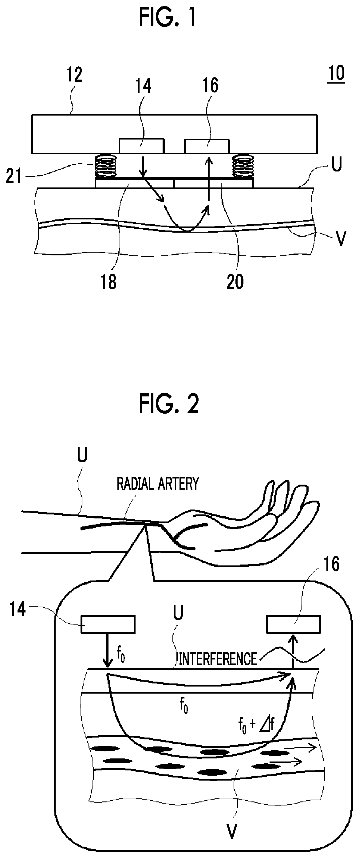
The present invention provides a flow rate measuring device that can ensure sufficient signal intensity even with a low output light source. This is achieved through a holding mechanism that keeps the distance between the light bending member and the object constant. Overall, the device allows for accurate flow rate measurement even at low light levels.

Problems solved by technology

However, according to the study by the inventors, in the case of the wearable measuring device, it was found that there is a problem that the reflected light from the living body cannot be detected with the small irradiation intensity of laser light, although it is difficult to increase the laser output (irradiation intensity) for downsizing and power saving of the device.

Method used


Image

  • Flow rate measuring device
  • Flow rate measuring device
  • Flow rate measuring device

Examples


example 1

[0287][Preparation of Liquid Crystal Diffraction Element]

[0288](Formation of Alignment Film 1)

[0289]As the support, a triacetyl cellulose (TAC) film (ZRG40 manufactured by Fujifilm Corporation, a phase difference of 0) was prepared.

[0290]The following coating liquid for forming alignment film 1 was applied onto the support by spin coating. The support on which the coating film of the coating liquid for forming alignment film 1 was formed was dried using a hot plate at 60° C. for 60 seconds, so that an alignment film 1 was formed.

Coating Liquid for Forming Alignment Film 1The following material A for photo-alignment 1.00 part by massWater16.00 parts by massButoxyethanol42.00 parts by massPropylene glycol monomethyl ether42.00 parts by massMaterial A for Photo-Alignment-

[0291](Exposure of Alignment Film 1)

[0292]The alignment film 1 was irradiated with polarized ultraviolet rays (100 mJ / cm, using an ultra-high pressure mercury lamp), so that the alignment film 1 was exposed.

[0293](Form...

example 2

[0330]A flow rate measuring device was manufactured in the same manner as in Example 1 except that the holding mechanism was not provided, and the above-described evaluation was performed. That is, in Example 2, the laminate including the liquid crystal diffraction element was directly attached to the substrate.

example 3

[0331]A flow rate measuring device was manufactured in the same manner as in Example 1 except that the intersecting angle α of the two light rays was set to 16.5° in the formation of the alignment film 2, and the above-described evaluation was performed. It was confirmed that the single period of the alignment pattern of the liquid crystal layer 1 (liquid crystal diffraction element) formed on the alignment film 2 was 1.1 μm. The diffraction angle was 30°.


PUM


Abstract

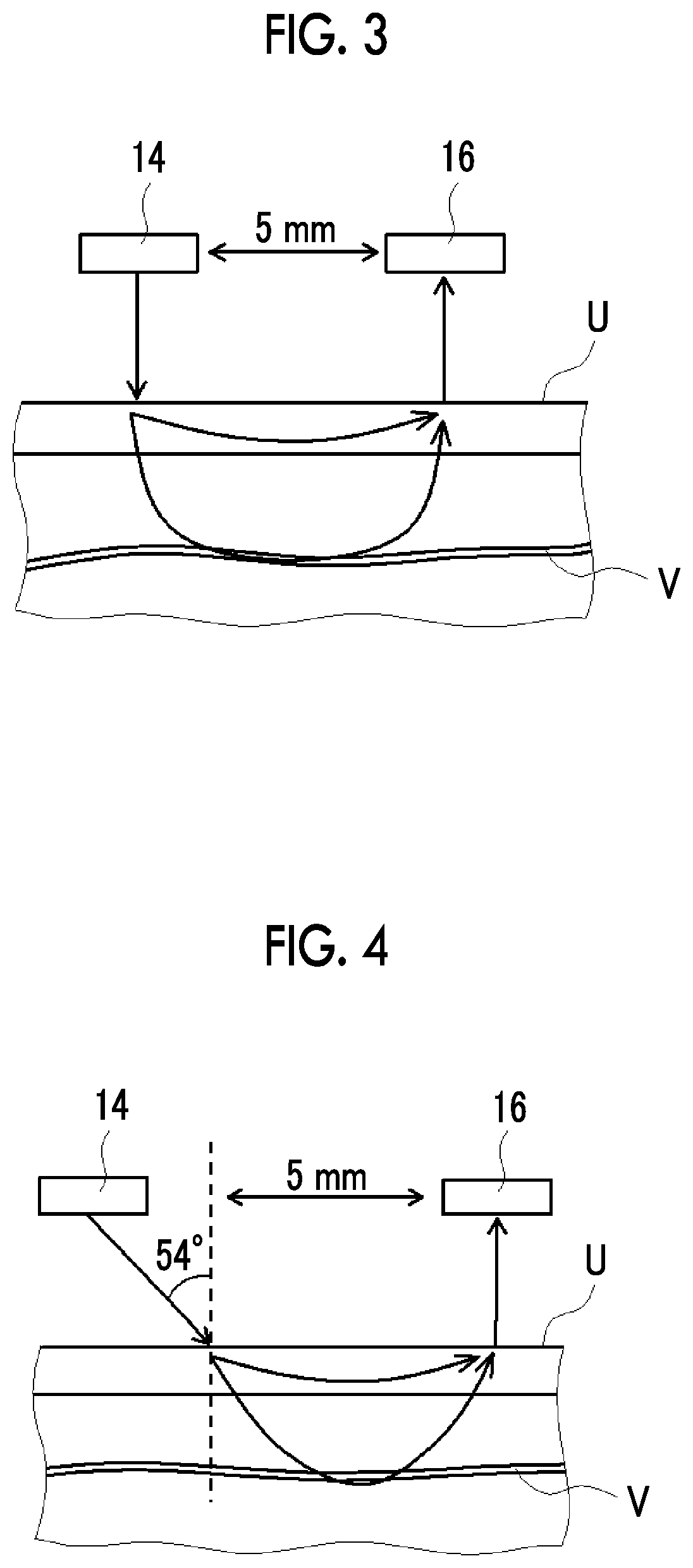
Provided is a flow rate measuring device capable of ensuring sufficient signal intensity even with a low output light source. The flow rate measuring device that detects a flow velocity of a fluid flowing through an object by a Doppler effect of light, the flow rate measuring device includes a light source unit that emits laser light to the object, a light receiving unit that receives the laser light scattered by the object, and a light bending member that bends the laser light emitted from the light source unit and causes the laser light to be inclined with respect to a surface of the object and incident on the surface.

Description

CROSS-REFERENCE TO RELATED APPLICATIONS[0001]This application is a Continuation of PCT International Application No. PCT / JP2020 / 035999 filed on Sep. 24, 2020, which claims priority under 35 U.S.C. § 119(a) to Japanese Patent Application No. 2019-177825 filed on Sep. 27, 2019. The above application is hereby expressly incorporated by reference, in its entirety, into the present application.BACKGROUND OF THE INVENTION1. Field of the Invention[0002]The present invention relates to a flow rate measuring device.2. Description of the Related Art[0003]There has been known a device that irradiates a living body with light and that detects the light reflected by the living body to acquire information regarding the living body, such as a blood flow velocity and a pulse wave. Further, there have been proposed a method of converting a pulse wave velocity by heartbeat measurement at a chest and pulse measurement at a fingertip into a blood pressure, and a method of converting a blood flow veloci...

Claims


Application Information

Patent Timeline
IPC IPC(8): G01F1/661G01F1/663
CPCG01F1/661A61B5/02108G01F1/663G01P5/26G01F1/704A61B5/0261
Inventor KASAHARA, TAKEHIRO
Owner FUJIFILM CORP
Why Eureka
Try Eureka