Image-taking lens apparatus

a technology of image-taking lens and lens body, which is applied in the field of image-taking lens body, can solve the problems of inability to make the thickness of the image-taking lens body smaller than the sum, inability to make the digital camera satisfactorily compact, etc., and achieves the effect of shortening the physical axial distance of the object light, high optical performance, and high refractive index of the prism

Active Publication Date: 2005-11-24
KONICA MINOLTA PHOTO IMAGING
View PDF7 Cites 44 Cited by
  • Summary
  • Abstract
  • Description
  • Claims
  • Application Information

AI Technical Summary

Benefits of technology

[0019] According to the present invention, since the prism is so designed as to fulfill conditional formula (1), it is possible to realize an image-taking lens apparatus incorporating an image-taking lens system that offers high optical performance despite being compact. The higher the refractive index of the prism, the shorter the physical axial distance that the object light travels when passing through the prism. Thus, by using a prism that fulfills conditional formula (1), it is possible to reduce both the total length of the image-taking lens system and the dimension thereof along the thickness direction thereof, and thus it is possible to realize an optically equivalent construction in a more compact space. Moreover, since the total length of the zoom lens system can be reduced without giving a curvature to the entrance-side or exit-side surface of the prism, it is easy to manufacture the prism, leading to lower costs. By using image-taking lens apparatuses according to the present invention in devices such as digital cameras and portable data devices, it is possible to contribute to making such devices slim, lightweight, compact, inexpensive, high-performance, intelligent, and otherwise better.

Problems solved by technology

The biggest bottleneck in slimming down a camera is the thickness of the image-taking lens system from the surface closest to the object to the image surface.
However, with the collapsible construction, it is impossible to make the thickness of the image-taking lens apparatus smaller than the sum of the thickness of the lens system itself, the thickness of the image sensor, and the thickness of the optical filter components required by the image sensor.
This makes it impossible to make digital cameras satisfactorily compact.
Moreover, with the collapsible construction, the lens needs to be moved out when the camera is used, and this requires a complicated lens barrel construction.
This results in high manufacturing difficulty, leading to great degradation in image quality and a great increase in costs.
Furthermore, in a construction where the lens is moved out after the camera power is turned on, it takes time to complete the preparations for photographing.
This makes the user more likely to miss good opportunities for photographing.
That is, the prism has too low a refractive index, making the total length of the zoom lens systems unduly long.
Moreover, here, the technique of bending the optical axis is not used to effectively achieve slimming-down.
Thus, the obtained image-taking lens systems cannot be said to be satisfactorily compact.
Most of these zoom lens systems include a plastic prism of which both the entrance-side and exit-side surfaces are given curvatures, and thus many of them are supposed to be difficult to manufacture.
The zoom lens systems disclosed in Publication 3 include a glass prism of which both the entrance-side and exit-side surfaces are given curvatures, and such a glass prism is more difficult to manufacture than a plastic equivalent.
When consideration is given to the technology of glass molding and of plastic injection molding and to the after-molding machining of a prism, giving curvatures to a prism involves many problems to be solved in terms of the manufacture of the prism.
For example, manufacturing errors arising in integral molding may result in degraded performance, and the manufacturing difficulty of integral molding itself may result in higher costs.
Thus, the obtained image-taking lens systems cannot be said to be satisfactorily compact.

Method used


Image

  • Image-taking lens apparatus
  • Image-taking lens apparatus
  • Image-taking lens apparatus

Examples


examples

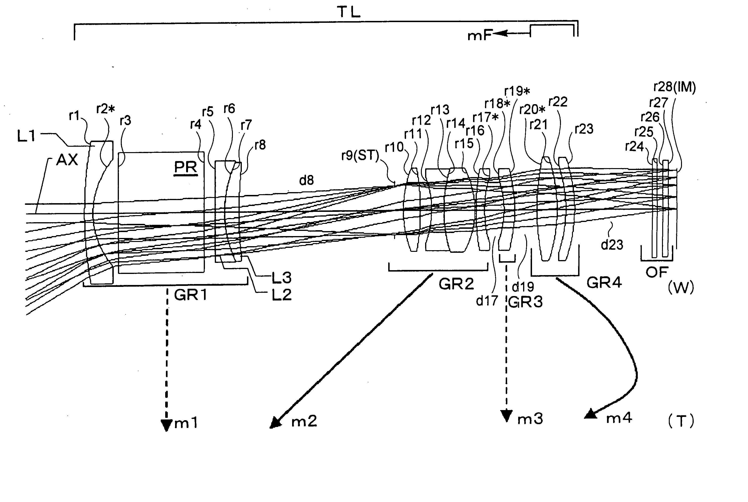
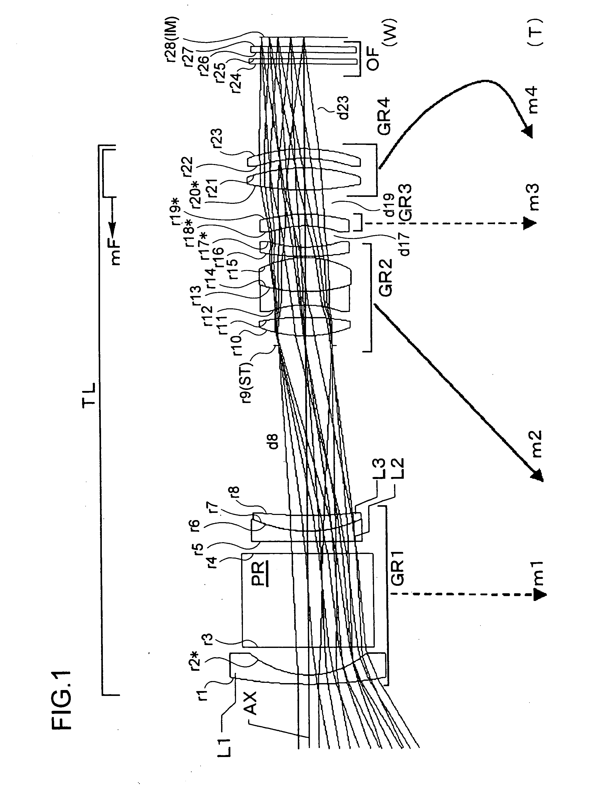
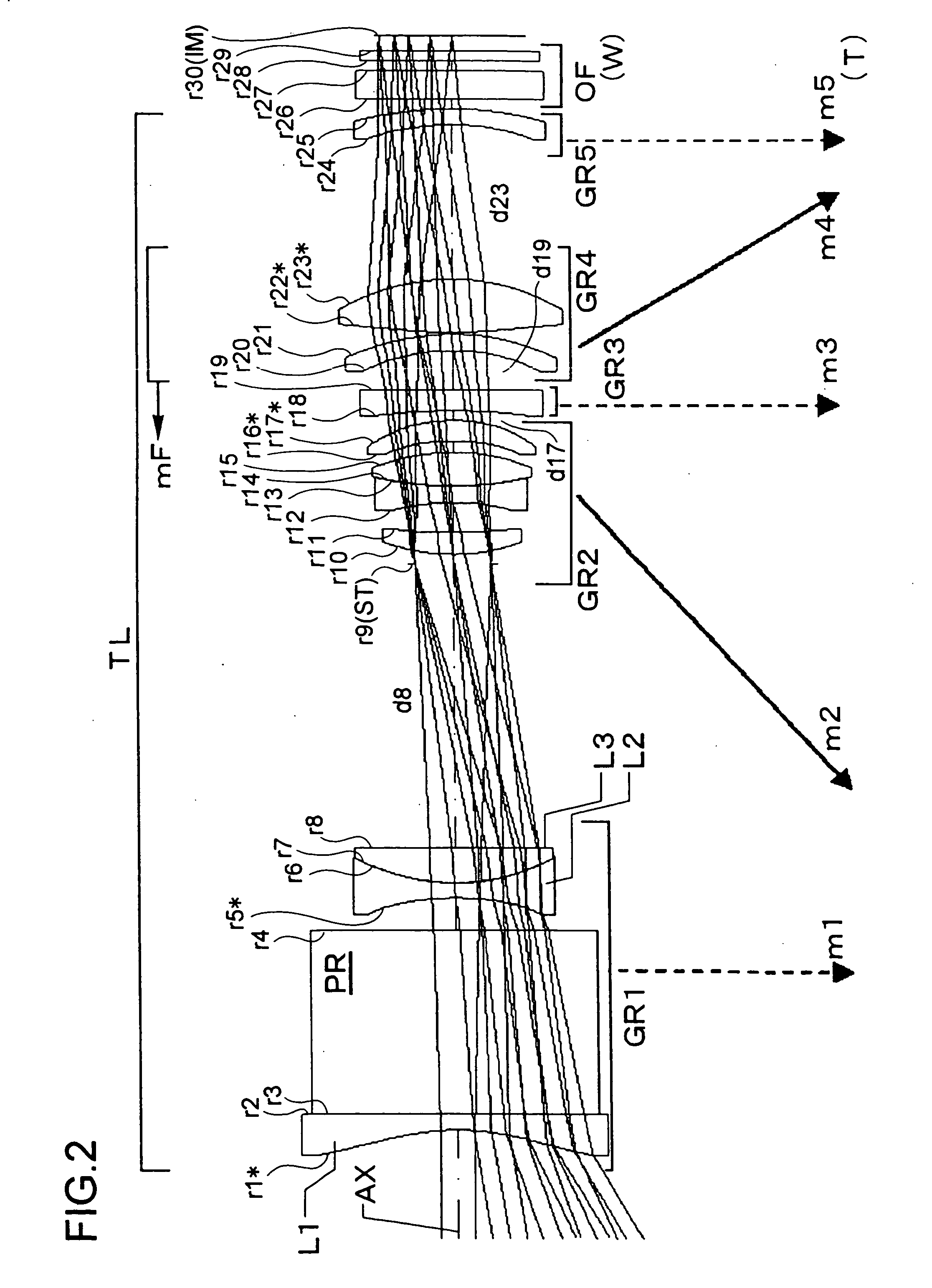
[0115] Hereinafter, the construction and other features of practical examples of the zoom lens system used in an image-taking lens apparatus embodying the present invention will be presented with reference to their construction data and other data. Examples 1 to 5 presented below are numerical examples corresponding to the first to fifth embodiments, respectively, described hereinbefore, and therefore the optical construction diagrams (FIGS. 1 to 10) of the first to fifth embodiments also show the lens construction of Examples 1 to 5, respectively.

[0116] Tables 1 to 10 show the construction data of Examples 1 to 5. Table 11 shows the values of the conditional formulae and the data related thereto as actually observed in each example. In Tables 1, 3, 5, 7, and 9, λ0 represents the design wavelength (in nm), Y′max represents the maximum image height on the light-receiving surface SS of the image sensor SR (corresponding to the distance from the optical axis AX, in mm), and f and Fno ...


PUM


Abstract

An image-taking lens apparatus has an image sensor for converting an optical image of a subject into an electrical signal and an image-taking lens system for forming the optical image on the image sensor. The image-taking lens system includes a prism for bending the optical path, and the refractive index of the prism fulfills a prescribed conditional formula.

Description

[0001] This application is based on Japanese Patent Application No. 2004-153091 filed on May 24, 2004, the contents of which are hereby incorporated by reference. BACKGROUND OF THE INVENTION [0002] 1. Field of the Invention [0003] The present invention relates to an image-taking lens apparatus, and more particularly to an image-taking lens apparatus (used as a main component of, for example, a digital still camera, digital video camera, or camera incorporated in or externally fitted to a personal computer, mobile computer, cellular phone, personal digital assistant, or the like) that optically takes in an image of a subject through an image-taking lens system and then outputs it as an electrical signal by means of an image sensor. The present invention relates, in particular, to an image-taking lens apparatus provided with a compact image-taking lens system, and to a slim camera provided with such an image-taking lens apparatus. [0004] 2. Description of Related Art [0005] In recent ...

Claims


Application Information

Patent Timeline
Patent Type & Authority Applications(United States)
IPC IPC(8): G02B5/04G02B7/10G02B13/18G02B15/14G02B15/16G02B15/167G02B15/177G02B15/20G02B17/04G03B9/10H04N5/225
CPCG02B5/04G02B17/045G02B15/177G02B15/144511G02B15/143507G02B15/144507G02B15/145511
Inventor YAGYU, GENTAYAMAGUCHI, SHINJIKONNO, KENJIKOJIMA, KAORI
Owner KONICA MINOLTA PHOTO IMAGING
Why Eureka
Try Eureka