
Radio base station and mobile communication system

a mobile communication system and radio base station technology, applied in the field of radio base station and mobile communication system, can solve the problems of deteriorating terminal output, unable to select above hand-over method a), and unable to communicate, so as to shorten the time of retransmission data or ordinary data at hand-over tim

Inactive Publication Date: 2005-11-24
FUJITSU LTD
View PDF9 Cites 47 Cited by
  • Summary
  • Abstract
  • Description
  • Claims
  • Application Information

AI Technical Summary

Benefits of technology

[0057] It is accordingly an object of the present invention to provide a radio base station and a mobile communication system wherein in the above-noted method c), the transmission time of retransmission data or ordinary data at hand-over time is shortened, thereby securing a transmission assignment time.
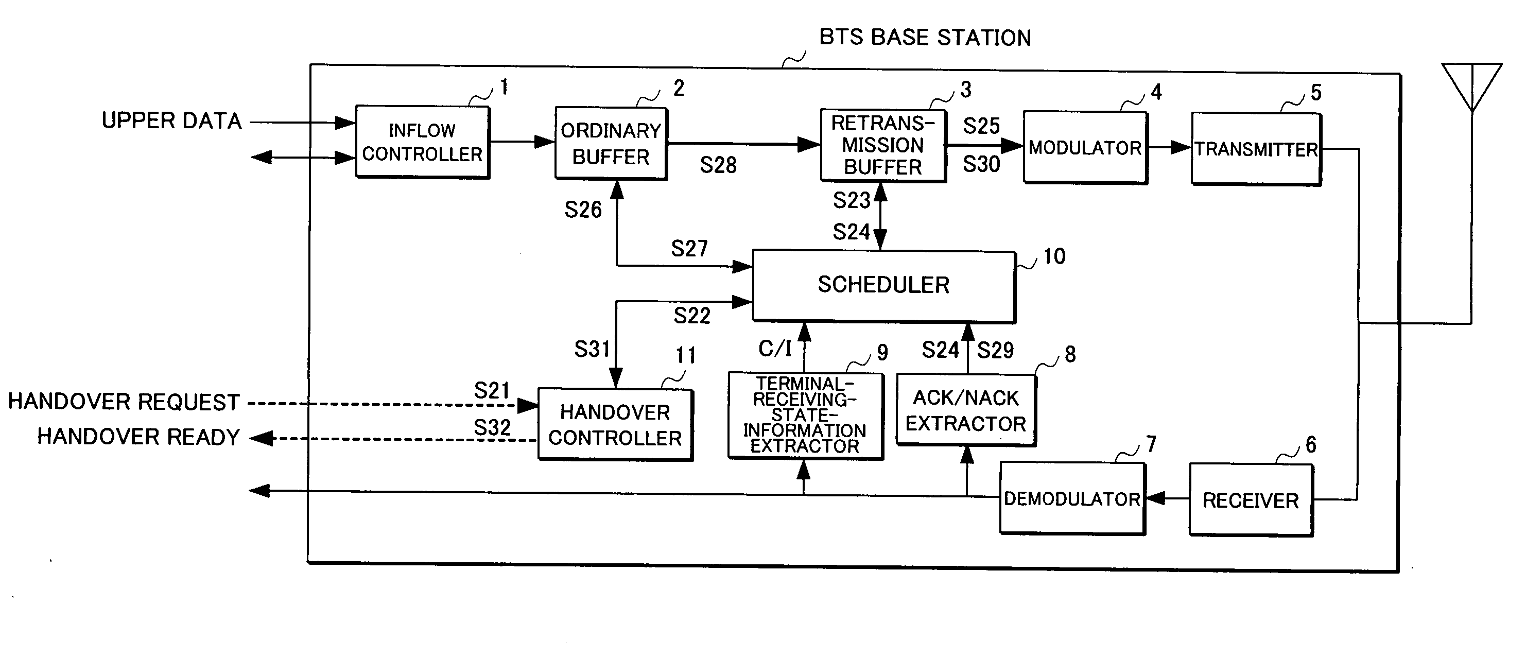
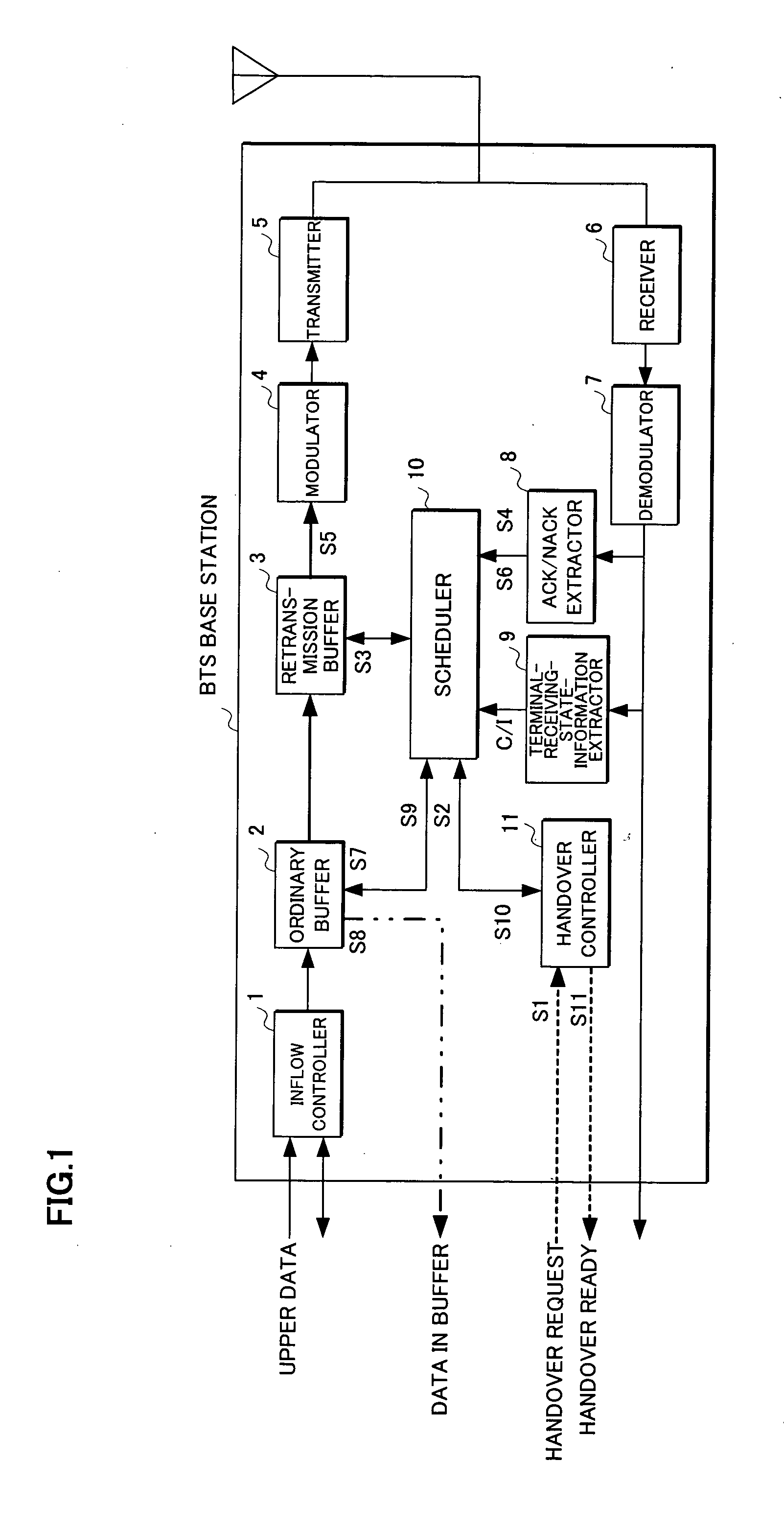
[0059] Namely, in the present invention, an output signal of the extractor is a NACK signal in case a received signal includes a retransmission request or an ACK signal in case ordinary data are requested, so that based on the output signal the scheduler controls the transmission of communication data to a terminal which is held in a buffer.
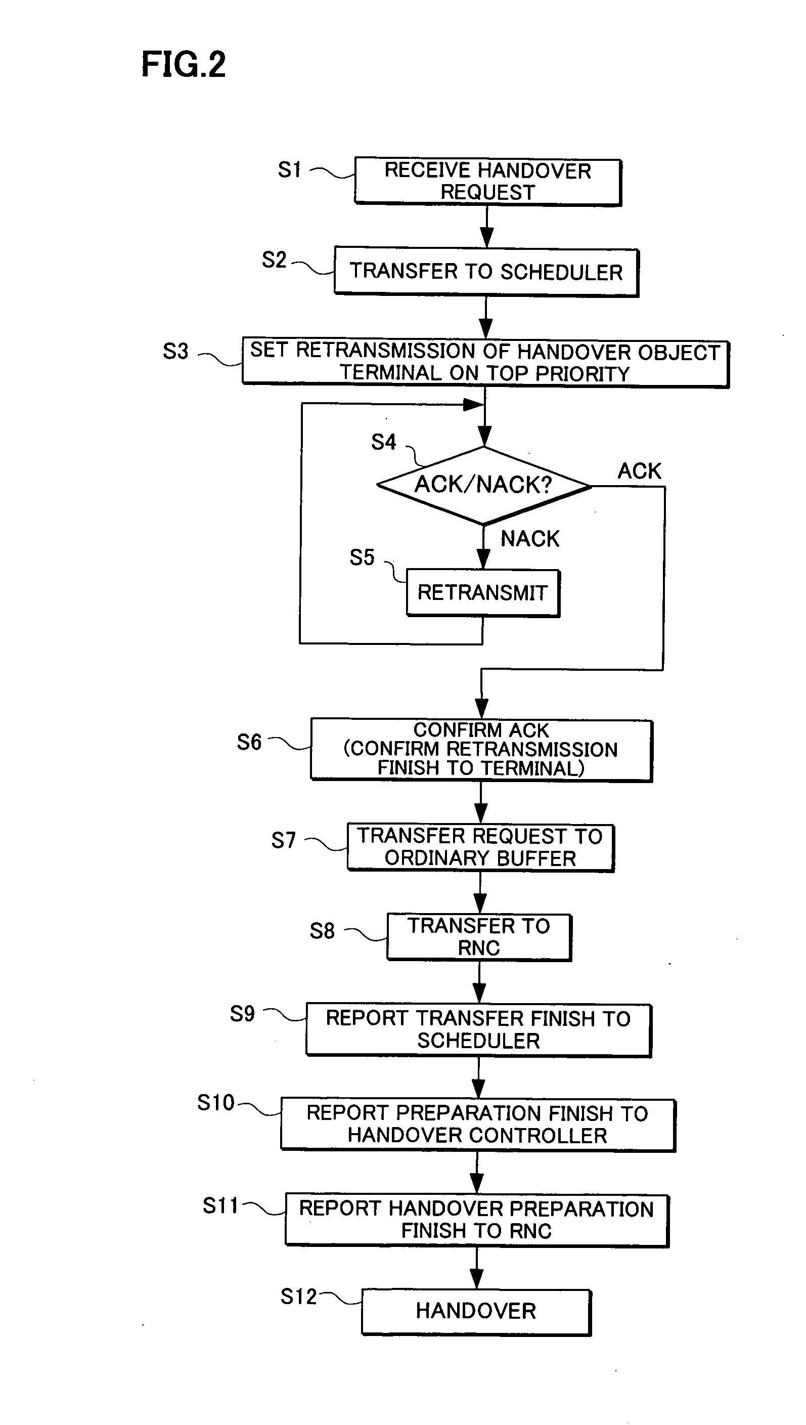
[0061] Thus, regardless of a reception status or service indicated by C / I etc of the hand-over object terminal, the order of data transmission at the scheduler is raised or advanced, which is equivalent to the transmission assignment time being relatively increased, whereby the data transmission to the hand-over object terminal is completed before the hand-over to shorten the time required for the hand-over.
[0066] Namely, since data are flowed into the radio base station even at hand-over time, a preferential data transmission at hand-over time is made possible more surely by suppressing the data inflow at the inflow controller preliminarily.

Problems solved by technology

As a result, it is disadvantageous that the throughput of the terminal is deteriorated or any communication is disabled at the worst case.
The above hand-over method a) cannot be selected because the data are lost.
The method b) is the most practical method which, however, requires data transmission between base stations, different from the conventional method.

Method used


Image

  • Radio base station and mobile communication system
  • Radio base station and mobile communication system
  • Radio base station and mobile communication system

Examples


embodiment (

10)

Simulating Handover Time Based on Moving Speed of Terminal

[0221] While the embodiments (8) and (9) make controls by using the moving direction of the terminal, a similar determination is made possible by using a moving speed of the terminal.

[0222] An embodiment (10), performing such a control, is shown in FIGS. 24 and 25.

[0223] Namely, the base station BTS shown in FIG. 24, employs a terminal-moving-speed calculator 22, different from the embodiment (8) shown in FIG. 19 employing the moving terminal direction calculator 20. The operation of this embodiment will now be described along the flow chart shown in FIG. 25.

[0224] In the flow chart shown in FIG. 25, steps S131-S134 respectively correspond to steps S111-S114 in the flow chart of the embodiment (8) shown in FIG. 20, in which the terminal-moving-speed calculator 22 can calculate a moving speed V of the terminal by using the following equation by inputting two pieces of the terminal-position information PT1 and Pt2 respec...


PUM


Abstract

A radio base station and a mobile communication system where a hand-over request is detected and retransmission data is preferentially processed for a hand-over object terminal. A radio base station may include a buffer holding communication data for transmission to a terminal, an extractor extracting a communication request signal from a received signal, and a scheduler controlling transmission of the communication data based on an output signal of the extractor. Also a scheduler, upon detection of a hand-over request, controls transmission so as to preferentially perform the data transmission by raising an order of the data transmission for a hand-over terminal before hand-over.

Description

CROSS-REFERENCE TO RELATED APPLICATION [0001] This application is a continuation of International Application PCT / JP03 / 01710 filed on Feb. 18, 2003, now pending, the contents of which are herein wholly incorporated by reference.BACKGROUND OF THE INVENTION [0002] 1. Field of the Invention [0003] The present invention relates to a radio base station and a mobile communication system, and in particular to a radio (wireless) base station and a mobile communication system utilizing for example W-CDMA (Wideband-Code Division Multiple Access) and the like. [0004] 2. Description of the Related Art [0005] Recently, developments of W-CDMA are expected as one of the high-speed packet communication methods in the next generation mobile communication system. [0006] In a mobile communication system using packets such as W-CDMA, the standards have been reviewed in 3GPP (3rd Generation Partnership Project), where with protocols prescribed thereby, packet communications are performed between a radio...

Claims


Application Information

Patent Timeline
IPC IPC(8): G03C1/005G03C7/392G03C7/396H04W36/02H04W36/08H04W36/32H04W88/08
CPCG03C1/005G03C7/39244G03C7/39296G03C7/396H04W36/02H04W88/08H04W36/32G03C2001/0854H04W36/324H04W36/322
Inventor ODE, TAKAYOSHIOTANARI, JUNJI
Owner FUJITSU LTD
Learn More