Constant emissivity deposition member

a deposition member and constant emissivity technology, applied in the direction of solid-state diffusion coating, crystal growth process, coating, etc., can solve the problems of substrate temperature drift, low showerhead temperature, and low pyrolytic decomposition of mocvd precursors, so as to achieve the effect of altering the delicate balan

Inactive Publication Date: 2005-11-24
IBM CORP
View PDF5 Cites 8 Cited by
  • Summary
  • Abstract
  • Description
  • Claims
  • Application Information

AI Technical Summary

Benefits of technology

[0004] In a low pressure, cool wall CVD reactor, the substrate temperature is a matter of delicate balance between heat flows from the heater to the substrate and from the substrate to its surroundings. This delicate balance can be altered if the optical properties, i.e. the emissivity (ε), of some of the involved components changes. The emissivity ε is an inherent property of an object, defined as the ratio of the actual amount of electromagnetic radiation emitted by the object to the amount emitted by an ideal blackbody at the same temperature. The value of the emissivity ε is a fractional value between 0 and 1, with 1 being a perfectly emitting blackbody. Unfortunately, in actual practice the emissivity ε of a deposition member, or showerhead, is frequently subject to change as a result of repetitive operation. For instance, it is often found that pyrolytic decomposition of a MOCVD precursor, although minimized by low showerhead temperature, is not completely avoidable. As such material builds up it changes the showerhead from typically being a bright reflective surface to a dull grey-black absorptive surface. This emissivity change in the deposition member leads to substrate temperature drifts.

Problems solved by technology

Unfortunately, in actual practice the emissivity ε of a deposition member, or showerhead, is frequently subject to change as a result of repetitive operation.
For instance, it is often found that pyrolytic decomposition of a MOCVD precursor, although minimized by low showerhead temperature, is not completely avoidable.
This emissivity change in the deposition member leads to substrate temperature drifts.

Method used


Image

  • Constant emissivity deposition member
  • Constant emissivity deposition member

Examples


Embodiment Construction

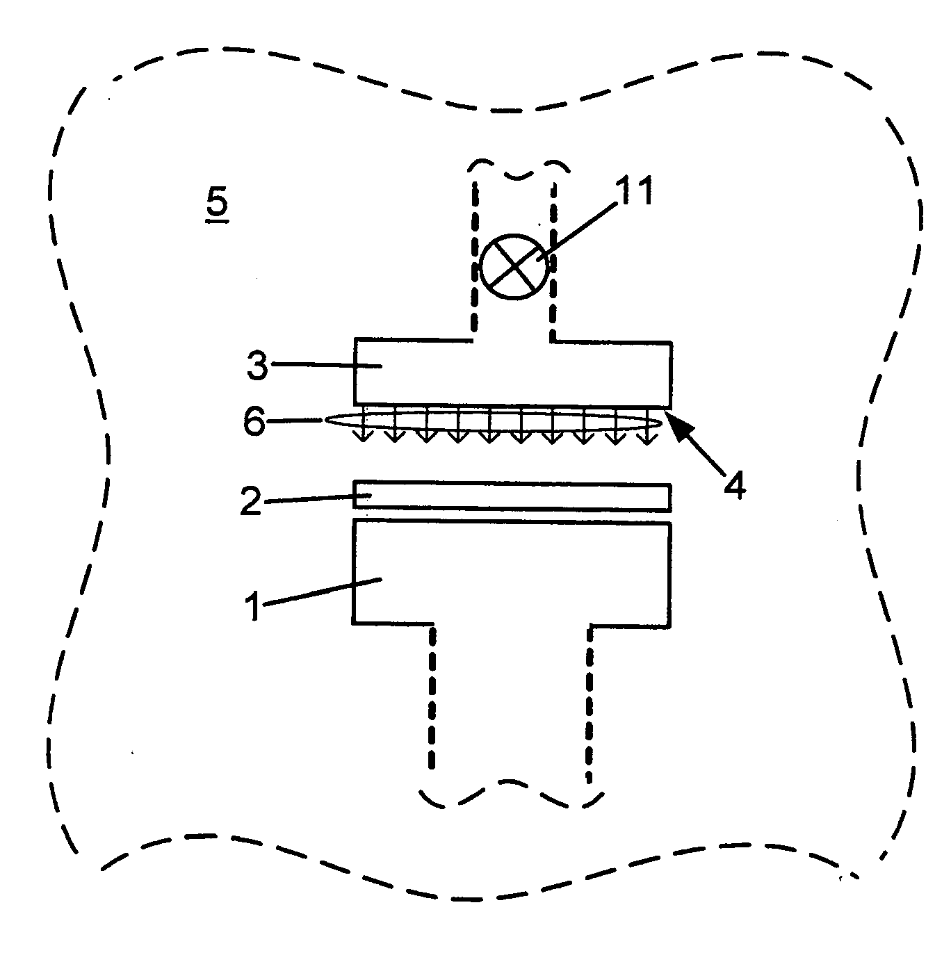
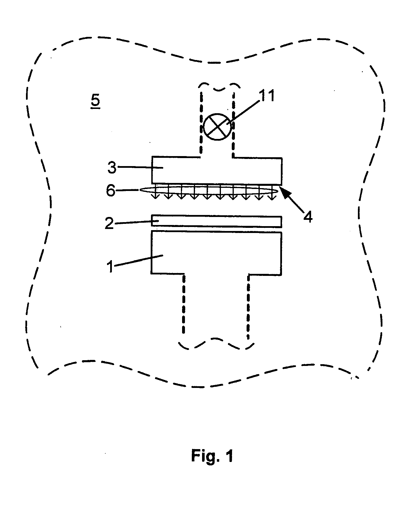
[0008]FIG. 1 shows a symbolic cross sectional view of a deposition apparatus, typically a low pressure deposition apparatus. Although the present invention is applicable to any apparatus used for depositing of material layers, the figure is closest to a chemical vapor deposition (CVD) a low pressure apparatus, as an exemplary embodiment. One skilled in the art would appreciate that in general such system are very complex. Consequently, the figure is depicting only those parts of the apparatus which are relevant for the present invention with the surrounding dashed lines indicating the rest of the system.

[0009] A deposition member 3, in case of a CVD, or MOCVD apparatus called a showerhead, is adapted to discharge at least one deposition material 6 during a low pressure deposition process. In an exemplary embodiment, such as MOCVD, deposition materials are typically precursor gases. However, in differing low pressure deposition apparatuses, for instance in MBE systems, the depositio...


PUM

PropertyMeasurementUnit
thickaaaaaaaaaa
thickaaaaaaaaaa
pressureaaaaaaaaaa

Abstract

A deposition member adapted for discharging a deposition material during a deposition process can acquire a coating during the deposition. Such an initial emissivity value is selected for the deposition member, before any of the coating became deposited, that the emissivity of the deposition member remains substantially unchanged during the deposition process. In a representative embodiment the deposition member is coated with an appropriate thin layer for achieving the selected emissivity value.

Description

FIELD OF THE INVENTION [0001] The present invention relates to the deposition of thin films in the course of fabricating semiconductor devices. BACKGROUND OF THE INVENTION [0002] Today's integrated circuits include a vast number of devices. Smaller devices are key to enhance performance and to improve reliability. Smaller devices entail ever more difficult manufacturing techniques, combined with more reliability and reproducibility requirements. Semiconductor devices are in need of a large variety of thin films, or layers; metallic, insulating, semiconducting. Over the years many thin layer deposition techniques have been devised. Many of these are so called low pressure deposition processes, which as the name implies, carry out the deposition at pressures well below the atmospheric region. Examples of such low pressure deposition techniques are: chemical vapor deposition (CVD) including metal organic chemical vapor deposition (MOCVD), molecular beam epitaxy (MBE), atomic layer depo...

Claims


Application Information

Patent Timeline
Patent Type & Authority Applications(United States)
IPC IPC(8): C23C16/44C30B1/00C30B35/00H01L21/20H01L21/285H01L21/36H01L21/44
CPCC23C16/4404H01L21/28556C30B35/00
Inventor MCFEELY, FENTON READYURKAS, JOHN JACOBMALHOTRA, SANDRASIMON, ANDREW
Owner IBM CORP
Why Eureka
Try Eureka