Board connecting component and three-dimensional connecting structure using thereof

a three-dimensional connection and connecting component technology, applied in the direction of coupling contact members, fixed connections, coupling device connections, etc., can solve the problems of large stress added to the joint of a pin connector, difficulty in narrowing the connection pitch, and difference in size, so as to improve shock resistance and high shock resistance. , the effect of high shock resistan

Inactive Publication Date: 2005-11-24
PANASONIC CORP
View PDF5 Cites 35 Cited by
  • Summary
  • Abstract
  • Description
  • Claims
  • Application Information

AI Technical Summary

Benefits of technology

[0021] This makeup facilitates elastic deformation of the flexibly changing part of the lead terminal, when joining two pieces of boards such as module boards, and this board connector. This results in absorbing an impact force by this flexibly changing part even if the external force is added. Further, respective boards do not need to provide through-holes for connecting between these boards. This makeup allows the lead terminals of the board connector and circuit patterns of the board connected to these lead terminals, to be formed in a fine pitch. Consequently, three-dimensional connecting structure with high reliability can be implemented that is capable of fine-pitch connection and does not cause damage in the joint and others, even if a large impact force such as a drop impact is added.
[0034] The board connector according to the present invention is provided with a flexibly changing part that exposes a plurality of lead terminals made of a conductive material having spring elasticity, through one of the wall surface of the housing, and extends these lead terminals along this wall surface to the top end surface, being spaced from the wall surface and top end surface. With this makeup, even if a large impact force such as an drop impact is added to the three-dimensional connecting structure joined with this board connector, this flexibly changing part absorbs the impact force, largely improving shock resistance. Consequently, in spite of fine-pitch connection, a three-dimensional connecting structure with high shock resistance can be implemented.BRIEF DESCRIPTION OF THE DRAWINGS

Problems solved by technology

However, in the connection method by a pin connector, a large stress is added to the joint of a pin connector with the difference in fluctuation in size due to temperature change between members composing the joint, or with an external impact force.
However, such a structure, although a thermal stress can be absorbed, disables circuit patterns or electronic parts to be implemented in a connection region and also makes it difficult to narrow the connection pitch.

Method used


Image

  • Board connecting component and three-dimensional connecting structure using thereof
  • Board connecting component and three-dimensional connecting structure using thereof
  • Board connecting component and three-dimensional connecting structure using thereof

Examples


first embodiment

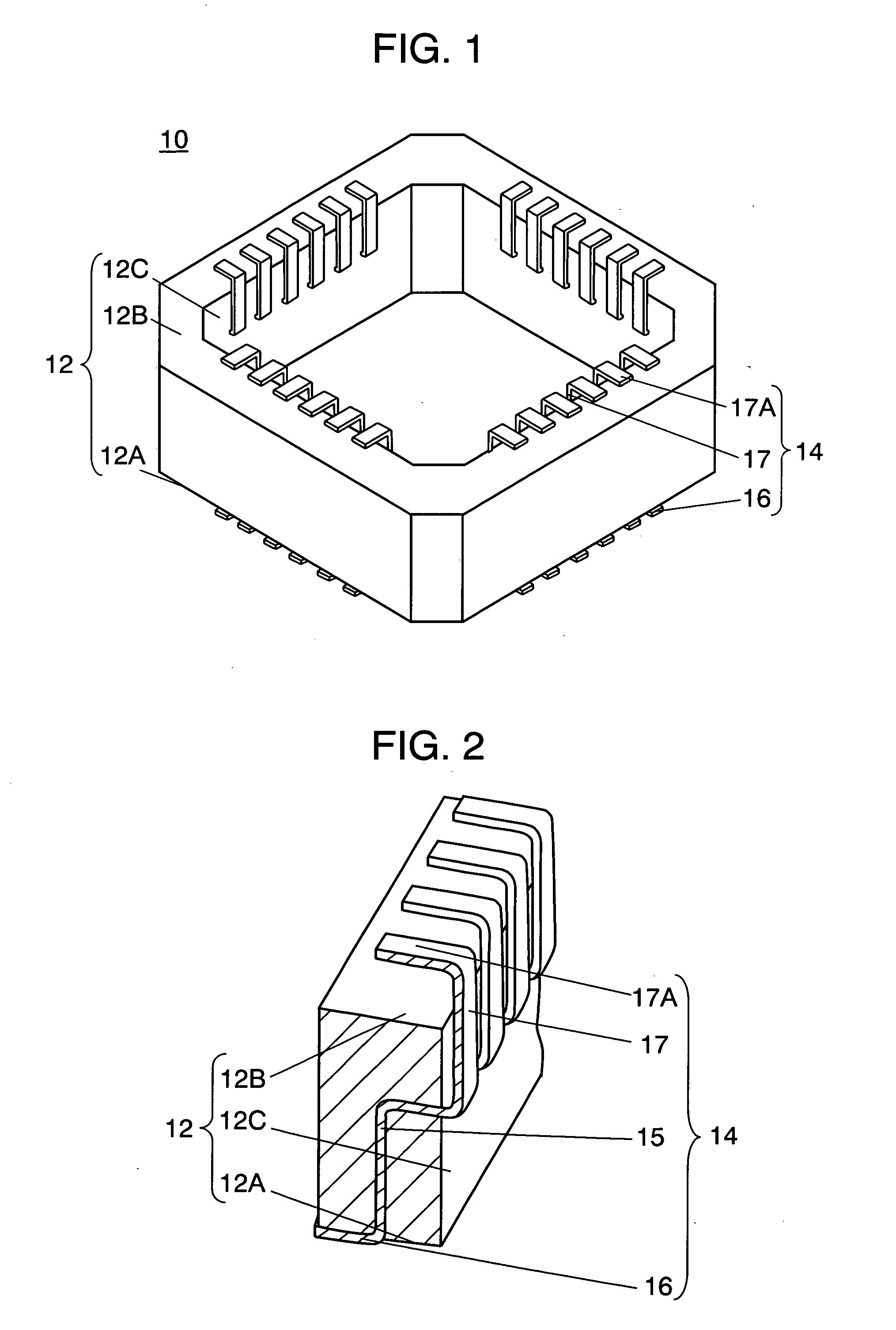
[0049]FIG. 1 is an external perspective view of board connector 10 according to the present invention. FIG. 2 is a perspective view of the cutaway substantial part for illustrating the structure of lead terminal 14 of this board connector 10.

[0050] Housing 12, made of resin such as liquid crystal polymer, polyphenylene sulfide, or polybutylene terephthalate, has a shape of quadrangle frame with its four angles respectively chamfered, in this embodiment. Still, the cross section is a vertically long rectangle as shown in FIG. 2. Lead terminals 14, made of a thin metal plate with high spring elasticity, are allocated on housing 12 at a given pitch, and part of them are buried in housing 12 to be fixedly retained. These lead terminals 14, as shown in FIG. 2, are composed of buried part 15 buried in housing 12; bottom end joint 16 provided on housing 12, near bottom end surface 12A; and flexibly changing part 17 rising from around the central part of inner wall 12C of housing 12 along i...

second embodiment

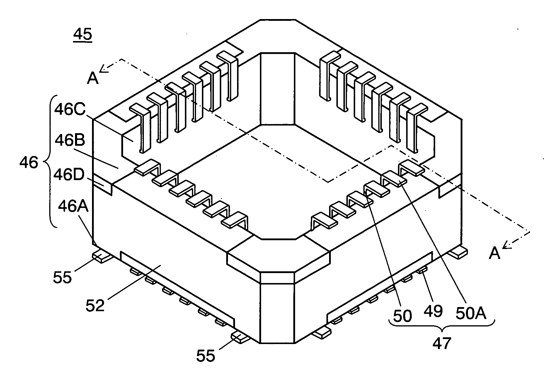
[0070]FIG. 6 is an external perspective view of board connector 45 according to the present invention. FIG. 7 is a perspective view of the cutaway substantial part for illustrating the structure of lead terminal 47 and shield layer 52 of this board connector 45.

[0071] The basic makeup of board connector 45 according to the embodiment is the same as that of board connector 10 described in the first embodiment. That is, housing 46, made of resin such as liquid crystal polymer, polyphenylene sulfide, or polybutylene terephthalate, has a shape of a quadrangle frame with its four angles respectively chamfered also in this embodiment. Still, the cross section is also a vertically long rectangle as shown in FIG. 7.

[0072] In the frame part of housing 46, lead terminals 47 made of a thin metal plate with high spring elasticity, are allocated at a given pitch, and part of them are buried in housing 46 to be fixedly retained. These lead terminals 47, as shown in FIG. 7, are composed of buried...


PUM


Abstract

The present invention includes a plurality of lead terminals made of a conductive material having spring elasticity; and insulative housing that buries a part of the region of lead terminal and fixedly retains a plurality of lead terminals in an arrangement having been set in advance. Lead terminal is composed of a buried part that is a part of lead terminal buried in housing; bottom end joint that is extended from one end of the buried part, is exposed through bottom end surface of housing, and extracted in width direction of bottom end surface; and flexibly changing part that is exposed from another end of the buried part through one wall surface orthogonal to bottom end surface, and is extended along this wall surface to top end surface facing to bottom end surface, being spaced from wall surface and top end surface.

Description

BACKGROUND OF THE INVENTION [0001] 1. Field of the Invention [0002] The present invention relates to a board connecting component (hereinafter, referred to as “board connector”) that connects a plurality of boards mounting electronic parts such as semiconductor devices (hereinafter, referred to as “IC”) and chip parts, and to a three-dimensional connecting structure using the board connector. [0003] 2. Background Art [0004] Conventionally, a board connector for connecting between boards such as module boards mounting electronic parts such as ICs and chip parts uses a multi-contact connector composed of plug and socket parts, or a pin connector with a plurality of contact pins fixed through a resin spacer. [0005]FIG. 10 is a sectional view showing a makeup in which two pieces of module boards 110 and 120 are connected by means of conventional pin connector 100. Pin connector 100 is composed of resin spacer 102; and a plurality of metal contact pins 104 fixed through this resin spacer...

Claims


Application Information

Patent Timeline
Patent Type & Authority Applications(United States)
IPC IPC(8): H01R12/00H01R13/24H01R33/76H05K1/14
CPCH01R9/096H05K1/144H05K3/3426H05K2201/2018H05K2201/10189H05K2201/10424H05K2201/042H01L2224/16225H01L2924/19105H01R12/52
Inventor ONO, MASAHIROKONDOU, SHIGERUNISHIKAWA, KAZUHIRONISHIDA, KAZUTOINOUE, HIROYUKIMIYAZAKI, OSAMUTAKEDA, HIROSHIEJIMA, TSUNEYUKI
Owner PANASONIC CORP
Why Eureka
Try Eureka