Intracorporeal probe with disposable probe body

Inactive Publication Date: 2005-11-24
TELEFLEX LIFE SCI LTD
View PDF26 Cites 32 Cited by
  • Summary
  • Abstract
  • Description
  • Claims
  • Application Information

AI Technical Summary

Benefits of technology

[0032] According to a further aspect of the present invention, a protective tip cap is provided for preventing the proximal migration of the impedance matching medium, or acoustic gel out of the tip. The tip cap may advantageously comprise a compressible, resilient sleeve, formed for example of synthetic rubber, which is selectively compressed by a rigid plastic structure around the probe body proximal to said tip, or sensor window. Preferably, the

Problems solved by technology

Hemodynamic monitoring is a useful and necessary tool in the management of critically ill patients which can present a wide variety of potential problems for clinicians which may result in an increase in mortality and morbidity of a patient.
), many patients who were otherwise deemed too risky to have open heart surgery could undergo these grossly invasive procedures.
However, use of the SGC presents its own risks to the patient.
Although the SGC was a major milestone in medical practice, widespread use of the SGC has led to increases in mortality and morbidity directly related to its invasiveness.
A significant drawback of such a probe is the need for disinfection and/or sterilization prior to use on a patient.
Such treatment is lengthy, expensive, and difficult to implement.
Care must be taken of the probe while it is being handled in this way since such a probe is fragile, inherently flexible, and the agents can be harmful.
In addition, it is necessary to repeat the process on each occasion that the probe is used, which is inconvenient and increases the risk of damaging the probe.
The device for the application of the jacket to such a long flexible probe body results in a number of difficulties.
For example, due to the typical length of an intracorporeal probe, particularly those intended for insertion in the esophagus, it has proven difficult in practice to place a thin, resilient jacket completely over the body of a probe without damaging the probe or the jacket.
Other difficulties a

Method used


Image

  • Intracorporeal probe with disposable probe body
  • Intracorporeal probe with disposable probe body
  • Intracorporeal probe with disposable probe body

Examples


Embodiment Construction

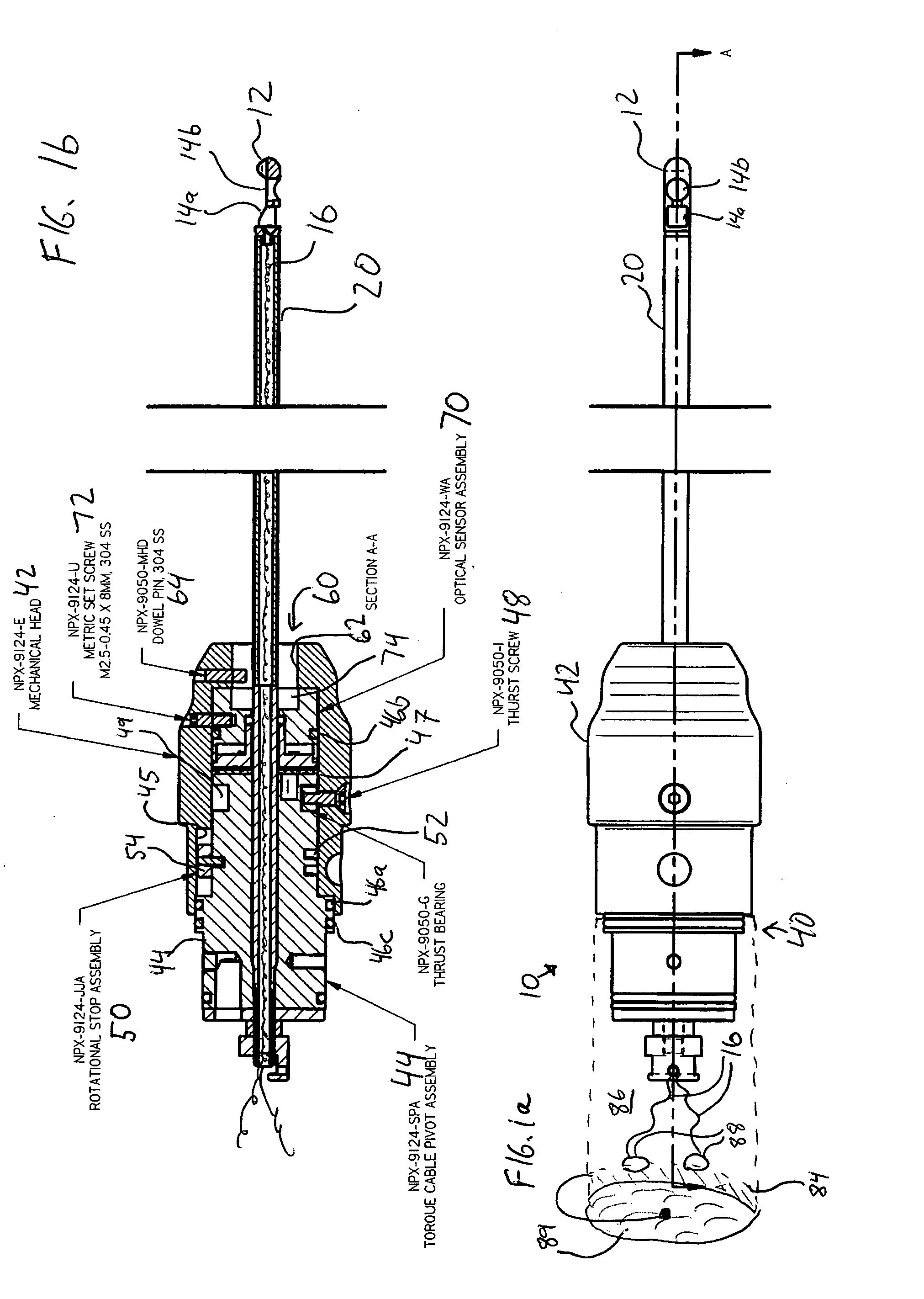
[0046] As shown in FIGS. 1a and 1b, an embodiment of probe 10 of the present invention is shown. Transducer cage 12 is at the distal end of probe 10 and is connected via sensor cable 20 to base 40 at the proximal end of probe 10.

[0047] Transducer cage 12 is preferably metallic and has a generally bullet-shaped cylindrical profile preferably having a cross sectional diameter of about 5 millimeter (mm) or less, which houses sensing elements 14a and 14b. Transducer cage 12 may also be provided with one or more grooves to facilitate distribution of ultrasonic gel over sensing elements 14. When probe 10 is to be used in place of a Swan Ganz Catheter for monitoring left ventricular function, the sensing elements are preferably crystal ultrasonic transducers, with sensing element 14a arranged at an angle which is offset 60 degrees relative to the angle of sensing element 14b. Transducer conductors 16 respectively carry electromagnetic signals to and from the sensing elements 14a and 14b, ...


PUM


Abstract

An ultrasonic probe for flow rate measurement is disclosed having a plurality of transducers mounted on a flexible cable configured to be inserted in a body cavity to obtain cardiac or other biometric telemetry. The flexible cable is provided with a disposable body which covers and microbially isolates the flexible cable and transducers. The disposable body is flexible and permits rotation of the flexible cable within it. Removal and replacement of the disposable body allows the probe to be used again without sterilization of the probe itself. A sensor window may be provided in the disposable body to allow transmission of ultrasonic signals, said window being provided with an anechoic surface treatment to reduce reception spurious ultrasonic echoes due to the material of the sensor window.

Description

FIELD OF THE INVENTION [0001] The present invention relates to a flexible intracorporeal probe, and more particularly to a probe having a flexible torque transmitting sensor portion covered by a flexible body which can be removed for disposal and replacement between uses. BACKGROUND OF THE INVENTION [0002] Hemodynamic monitoring is a useful and necessary tool in the management of critically ill patients which can present a wide variety of potential problems for clinicians which may result in an increase in mortality and morbidity of a patient. For example, with the development of the Swan Ganz Thermodilution Catheter (SGC, Edwards Laboratories, Irvine Calif.), many patients who were otherwise deemed too risky to have open heart surgery could undergo these grossly invasive procedures. However, use of the SGC presents its own risks to the patient. [0003] The SGC is a multi-lumen catheter that is placed through the right heart by way of internal jugular, subclavian or femoral veins. On...

Claims


Application Information

Patent Timeline
IPC IPC(8): A61B8/00A61B8/06
CPCA61B8/06A61B8/4422A61B8/12A61B8/00
Inventor BECKER, MATTHEWMACK, KEVINGERTLER, OTTOSCHAFER, MARKDENLINGER, RODLASSANDRO, ANGELAKNIEZEWSKI, STANLEYRANDOLPH, DANALASSANDRO, JASONREGAN, BILL
Owner TELEFLEX LIFE SCI LTD
Why Eureka
Try Eureka