
Method of monitoring gas turbine engine operation

a gas turbine engine and monitoring method technology, applied in the field of aircraft engines, can solve the problems of significant equipment and infrastructure in support, operator with little real-time information on engine health, etc., and achieve the effect of extending the operation of an aircraft-mounted gas turbine engin

Active Publication Date: 2005-11-24
PRATT & WHITNEY CANADA CORP
View PDF37 Cites 56 Cited by
  • Summary
  • Abstract
  • Description
  • Claims
  • Application Information

AI Technical Summary

Benefits of technology

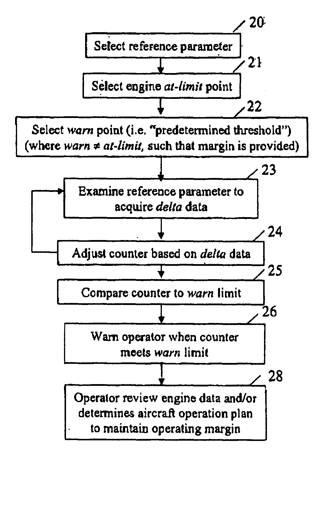
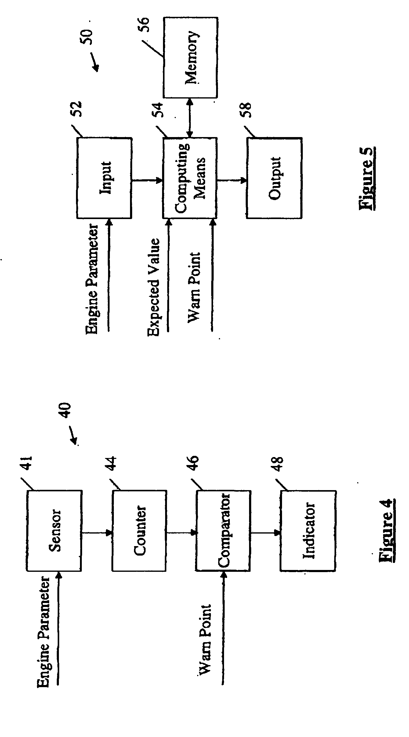
The present invention provides methods and systems for monitoring the performance of an aircraft-mounted gas turbine engine. The methods involve sensing engine conditions, comparing them against predetermined thresholds, adjusting a counter value based on the comparison, and setting a warning flag if the counter value meets certain criteria. The systems include a sensor, counter, comparator, and indicator to implement the methods. The technical effects of the invention include improving engine maintenance and operation efficiency, reducing downtime, and increasing safety.

Problems solved by technology

Such systems, however, require significant equipment and infrastructure in support, and typically provide the operator with little real time information on engine health.

Method used


Image

  • Method of monitoring gas turbine engine operation
  • Method of monitoring gas turbine engine operation
  • Method of monitoring gas turbine engine operation

Examples


example a

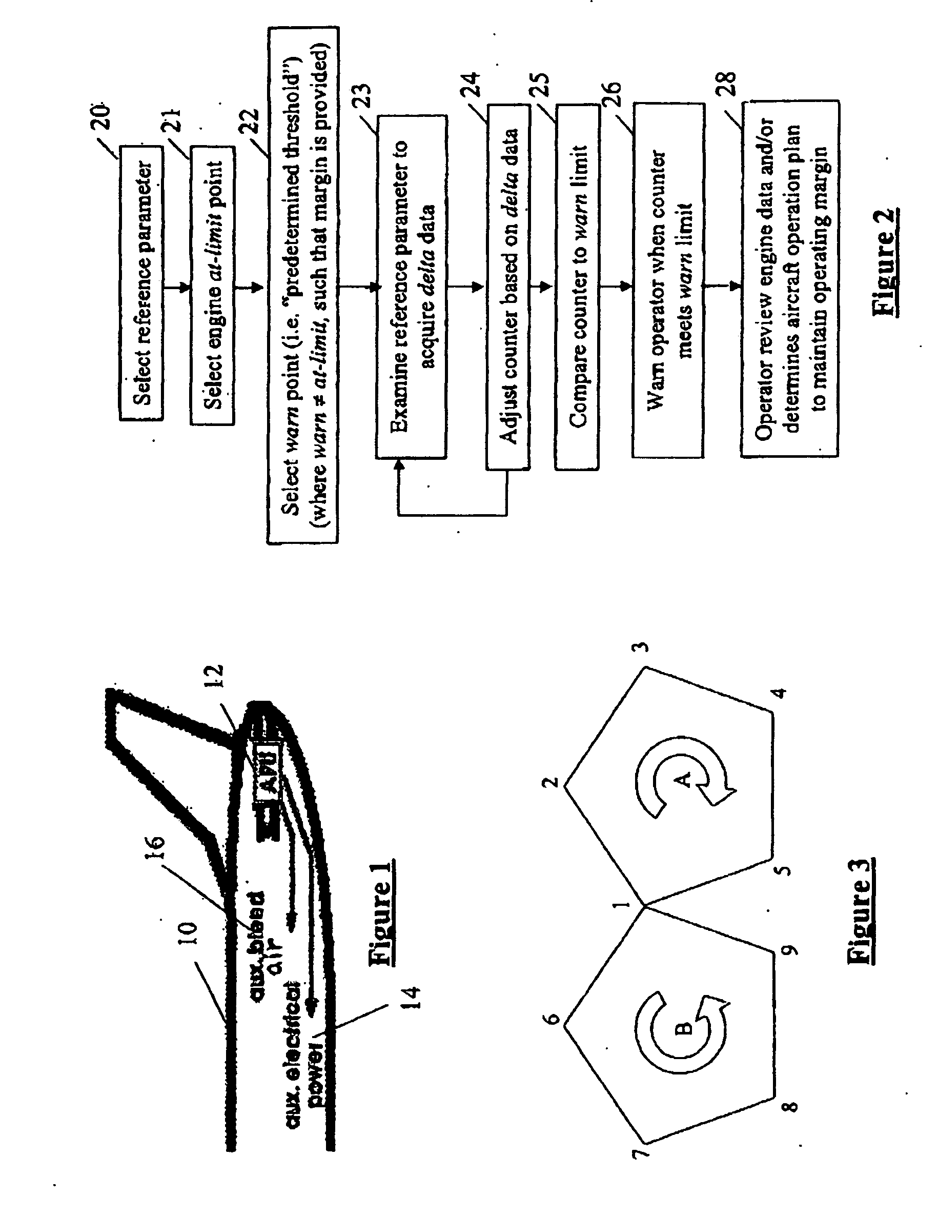
[0021] The engine EGT reference point is 641° C., above which IGV angle will be reduced by the APU control system to give preference to the electrical load on the APU. According to the invention, the IGV angle is monitored for a delta between the IGV angle scheduled and the IGV angle requested, and the counter increment / decrement values are selected as shown in Table 1. The counter limit is set at +15, at which time the warning flag is set. As aircraft flies the route indicated in FIG. 3, and the ambient conditions are experienced, and corresponding counter values are established, as set out in Table 2.

[0022] The continued and repeated exposure of the aircraft to condition on Loop A and Loop B would allow the APU to continue main engine start operation for 2.25 cycles before a maximum counter value of 15 is reached, at which time the warning flag “Impending—APU at Limit” would be set accordingly. Upon receiving such flag, the operator may then elect to schedule a maintenance task a...


PUM


Abstract

A system, method and apparatus for monitoring the performance of a gas turbine engine. A counter value Indicative of the comparison between the engine condition and the threshold condition is adjusted. The aircraft operator is warned of an impending maintenance condition based on the counter value and determines an appropriate course of action.

Description

FIELD OF THE INVENTION [0001] The invention relates to the field of engine health and trend monitoring, and In particular to applications related to aircraft engines. BACKGROUND OF THE INVENTION [0002] Engine health and trend monitoring typically involves the recording and monitoring of engine parameters, and subsequent monitoring and analysis of such parameters in an attempt to determine engine operating trends, and particularly those which may be indicative of an engine condition requiring maintenance. Some sophisticated systems include apparatus to upload engine data, upon aircraft arrival at its destination, to remote monitoring sites to provide on-going oversight of engine performance. Such systems, however, require significant equipment and infrastructure in support, and typically provide the operator with little real time information on engine health. SUMMARY OF THE INVENTION [0003] According to a first broad aspect of the present invention, there is provided a method of moni...

Claims


Application Information

Patent Timeline
Patent Type & Authority Applications(United States)
IPC IPC(8): F01D19/00F01D19/02F02C9/00F02C9/28F02D28/00G01M15/00G07C5/08
CPCF01D19/00G07C5/0816F05D2220/50F05D2240/12F05D2260/80F05D2270/303F05D2270/44
Inventor FEENEY, MARK EDWARDLESLIE, KEITH JOHNSYED, YUSUF RAZLHARTROPP, SIMON JOHN
Owner PRATT & WHITNEY CANADA CORP
Learn More