Vacuum chamber with two-stage longitudinal translation for circuit board testing

a circuit board and longitudinal translation technology, applied in the direction of resistance/reactance/impedence, testing circuits, instruments, etc., can solve the problems of inability to move the shuttle plate, the shuttle plate approach can provide a relatively high amount of friction, and the test delay or failur

Active Publication Date: 2005-11-24
CIRCUIT CHECK
View PDF2 Cites 11 Cited by
  • Summary
  • Abstract
  • Description
  • Claims
  • Application Information

AI Technical Summary

Benefits of technology

[0021] The present embodiment uses a dual-stage translation to bring a unit under test (UUT) into p

Problems solved by technology

Because, in at least some applications, circuit board testing is performed on substantially all devices on a production line or production facility, speed and reliability of testing can be especially important since delay or failure at a testing station can delay or interrupt the overall production in a production line or facility.
While this arrangement can achieve dual stage positioning, it has been found that such a shuttle plate approach can lead to delays or failures in testing.
For example, the shuttle plate approach can provide a relatively high amount of friction when the shuttle plate is moved laterally, particularly when components of the fixture are made of a G10 or similar relatively high-friction material.
This can lead to binding (inability of the shuttle plate to move smoothly to the second position or return to the first position).
Such binding can not only cause delays and slow down a production line or production facility but can cause failures which may require repairs or replacement of parts, thus creating a substantial interruption of production.
Pneumatic systems, unfortunately, are associated with certain undesirable qualities.
In general, this leads to a certain amount of flexure of the UUT as it is moved by the pneumatic actuators which can lead to poor contact with the probes in some locations of the UUT and, thus, inaccurate test results.
Furthermore, pneumatic systems are generally relatively massive (e.g., such as resulting in fixtures weighing 40 to 50 pounds more than vacuum systems).
Generally, this means that changing from one fixture to

Method used


Image

  • Vacuum chamber with two-stage longitudinal translation for circuit board testing
  • Vacuum chamber with two-stage longitudinal translation for circuit board testing
  • Vacuum chamber with two-stage longitudinal translation for circuit board testing

Examples


Embodiment Construction

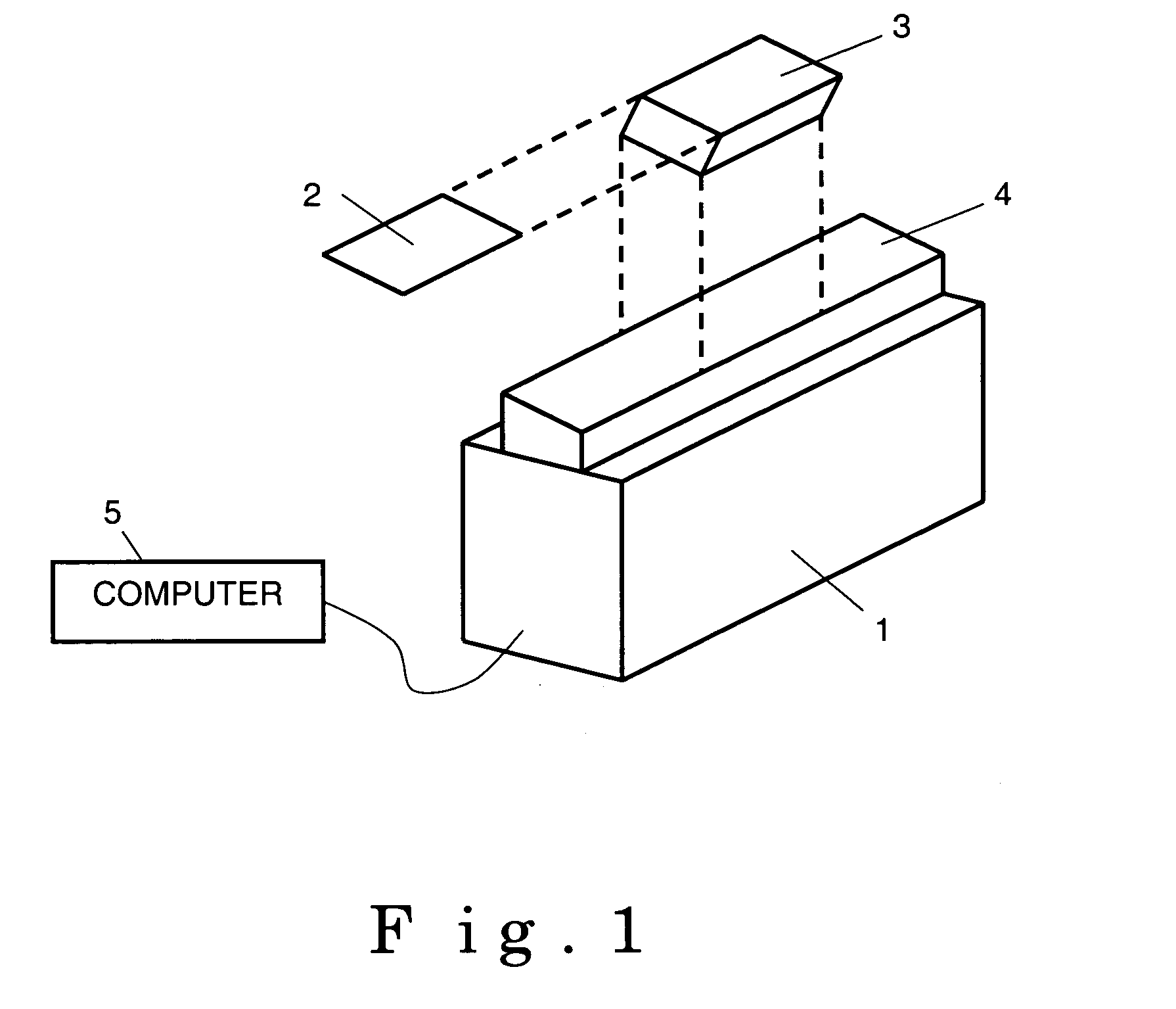
[0033] In a manufacturing environment for circuit boards, a final test will often be an electrical test, to ensure that each circuit board performs as required. Such tests are well-known in the industry, and may be performed by commercially available testers, such as Agilent Model 3070.

[0034] A basic schematic of a circuit board tester 1 is shown in FIG. 1. A circuit board, often referred to as a unit under test (UUT) 2, is mounted on a fixture 3 for the duration of the test, which provides a rugged mechanical mount for the UUT as well as a mechanical interface with other components in the tester 1. The fixture 3 is positioned on a bed 4, so that various electrical probes may make contact with specific locations on the UUT 2 and perform the desired tests. The probes may apply and measure voltages or currents at various locations on the UUT 2, and are controlled mechanically and electrically by the tester 1. A computer 5 may control the tester 1 and may record data from the tests.

[...


PUM


Abstract

A circuit board tester that uses a dual-stage translation to bring a unit under test (UUT) into physical and electric contact first with a series of tall probes, then with a series of short probes. Initially, the UUT is mounted on a support plate, and spaced apart from both the tall and short probes. First, in order to perform a functional test on the UUT, a first vacuum stage is engaged, and atmospheric pressure translates the UUT longitudinally until contact is made with a first hard stop, defining a first position. At this first position, the UUT is in contact with a series of tall probes, and is spaced apart from a series of short probes. After a function test is performed, a second vacuum stage is engaged in addition to, and independent of, the first vacuum stage. Atmospheric pressure translates the UUT longitudinally until contact is made with a second hard stop, defining a second position. At this second position, the UUT is in contact with both tall and short probes (the tall probes being appropriately spring-loaded so as to maintain physical and electric contact with the UUT without damaging the UUT). After an in-circuit test is performed, both vacuum stages are released, and the UUT returns to its initial location, spaced apart from both the tall and short probes. The UUT may be replaced with another part to be tested, and the cycle is repeated.

Description

CROSS-REFERENCE TO RELATED APPLICATIONS [0001] This is a Non-Provisional (Utility) patent application of provisional application Ser. No. 60 / 572263 filed May 18, 2004 and provisional application Ser. No. 60 / 572315 filed May 18, 2004STATEMENT REGARDING FEDERALLY SPONSORED RESEARCH OR DEVELOPMENT [0002] Not Applicable BACKGROUND OF THE INVENTION [0003] 1. Field of the Invention [0004] This invention is directed to test equipment, and more particularly to test equipment for circuit boards. [0005] 2. Description of the Related Art [0006] Circuit board testers are used for testing a variety of circuit boards or similar devices to assure that the circuit boards operate as intended. In at least one type of circuit board tester, such as Agilent Model No. 3070, Series 3, a separate device, referred to as a fixture, is used to position the circuit board such that a plurality of electrically conductive probes (which are part of, or coupled to, the tester) contact predetermined components or po...

Claims


Application Information

Patent Timeline
IPC IPC(8): G01R31/28G06F19/00
CPCG01R31/2808Y10S439/931
Inventor ADAMS, NEILEICKHOFF, STUARTHAMPLE, JON
Owner CIRCUIT CHECK
Why Eureka
Try Eureka