Data transfer control circuit, control apparatus and data transfer method

a control circuit and control circuit technology, applied in the direction of memory adressing/allocation/relocation, digital computers, instruments, etc., can solve the problems of complex control of software, limited transfer rate, and inability to achieve higher speed, so as to facilitate access to second memory, reduce the amount of use code, and effectively utilize cord memory

Inactive Publication Date: 2005-11-24
NEC ELECTRONICS CORP
View PDF29 Cites 11 Cited by
  • Summary
  • Abstract
  • Description
  • Claims
  • Application Information

AI Technical Summary

Benefits of technology

[0010] It is therefore an object of the present invention to provide a data transfer circuit, a control apparatus and a data transfer method, which can obtain the sufficient transfer rate that can handle the operation speed of the CPU, in the data transfer between the CPUs.
[0012] According to the present invention, the first CPU can recognizes the memory region in the second memory through the virtual memory space, thereby write and read data, even though the second memory belongs to the second CPU. Since the first CPU can easily access the second memory by using the data transfer control circuit, a device driver used for a communication control is not required. A use code amount can be reduced and a cord memory can be effectively utilized. The shared memory used for only the data transfer becomes unnecessary which can reduce a hardware quantity.

Problems solved by technology

That is, the transfer rate is limited by the performance of the serial I / F.
Thus, the higher speed cannot be attained.
Thus, the control of the software becomes complex.
If the perfect exclusion control cannot be carried out because of the duplication of semaphore flags caused by access competition, there may be a risk of an occurrence that the data is overwritten.
If a plurality of semaphore areas are prepared, this leads to the size increase in the shared memory and results in the cost increase.

Method used


Image

  • Data transfer control circuit, control apparatus and data transfer method
  • Data transfer control circuit, control apparatus and data transfer method
  • Data transfer control circuit, control apparatus and data transfer method

Examples


Embodiment Construction

[0020] Embodiment of a data transfer control circuit, a control apparatus and a data transfer method of the present invention will be described below with reference to the attached drawings.

[0021] At first, the configuration of the embodiment of the data transfer control circuit of the present invention and the control apparatus will be described.

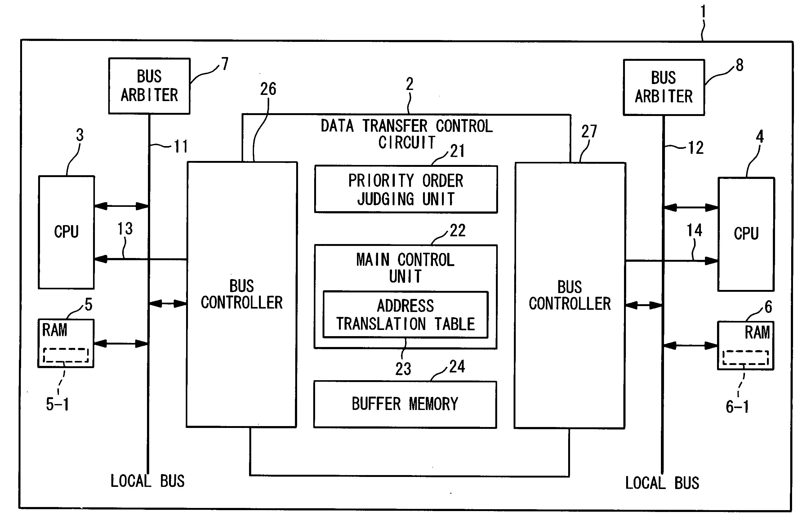
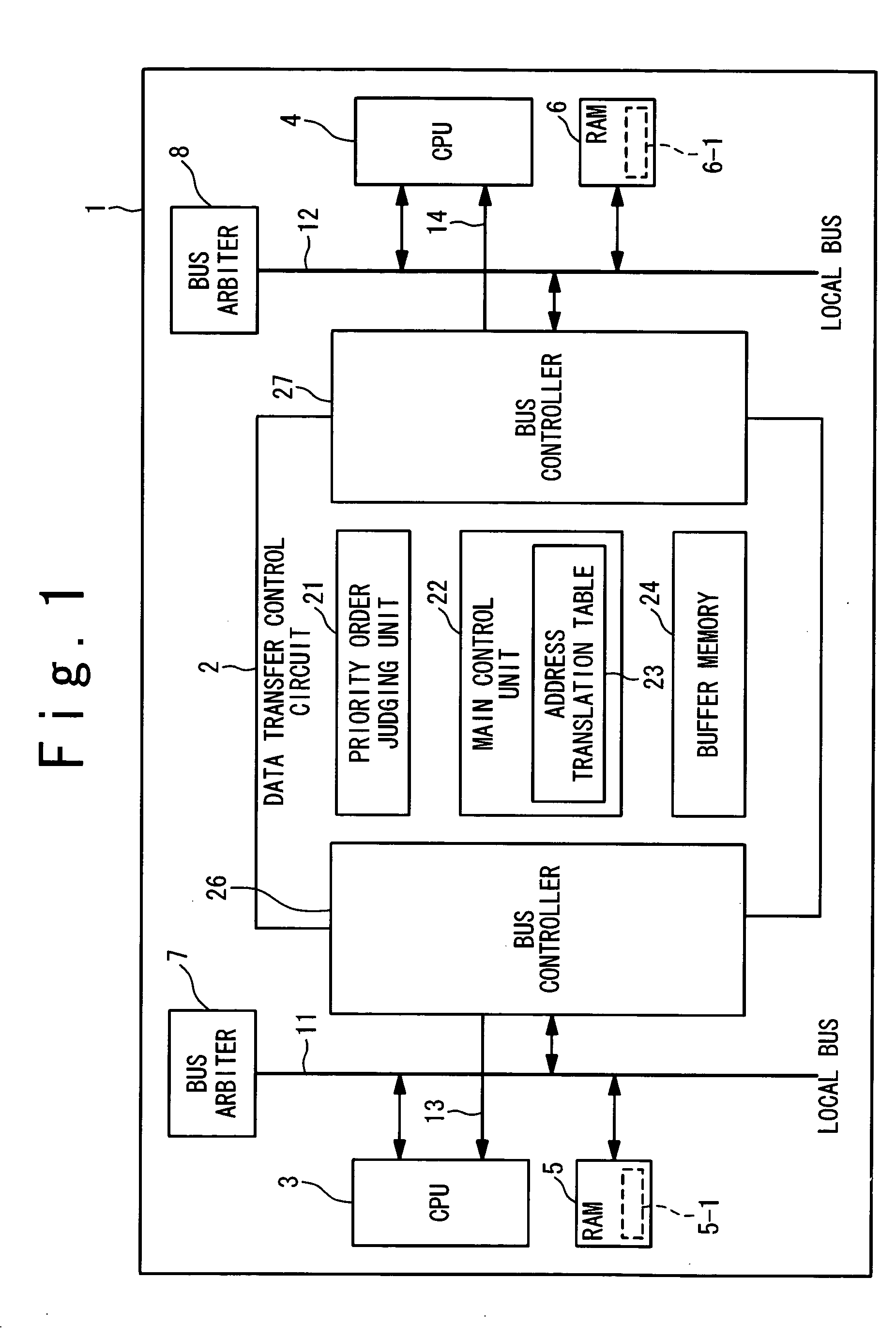
[0022]FIG. 1 is a block diagram showing the configuration of the embodiment of the control apparatus of the present invention. The control apparatus 1 includes a data transfer control circuit 2, a CPU (Central Processing Unit) 3, a CPU 4, a RAM (Random Access Memory) 5, a RAM 6, a bus arbiter 7, a bus arbiter 8, a local bus 11, a local bus 12, a signal line 13 and a signal line 14.

[0023] The CPU 3 as the first CPU is connected to the local bus11. The RAM 5 as the first memory is connected to the local bus 11 and belongs to the CPU 3. The RAM 5 has a memory region 5-1 assigned to the CPU 4, in addition to a memory region (not shown) assig...


PUM


Abstract

A data transfer control circuit is connected between a first bus and a second bus. The first bus is connected with a first CPU and a first memory. The second bus is connected with a second CPU and a second memory. The data transfer control circuit includes a temporary memory and a control unit. The temporary memory is configured to temporarily stores a first address and a first write data which are outputted by the first CPU through the first bus. The control unit is configured to translate the first address into a second address in the second memory with reference to an address translation table. The control unit occupies the second bus to write the first write data to the second address in the second memory through the second bus, when the first CPU releases the first bus after outputting the first address and the first write data to the data transfer control circuit through the first bus.

Description

BACKGROUND OF THE INVENTION [0001] 1. Field of the Invention [0002] The present invention relates to a data transfer control circuit, a control apparatus and a data transfer method. More particularly, the present invention relates to a data transfer control circuit, a control apparatus and a data transfer method with regard to a data transfer between CPUs (Central Processing Units). [0003] 2. Description of the Related Art [0004] In recent years, in order to improve a data processing performance, attention has been paid to a technique in which a data processing is shared and executed by a plurality of CPUs and a technique in which a data processing is executed in parallel by a plurality of CPUs. In these techniques, a data transfer is required between the plurality of CPUs. The data transfer method by using a serial transfer and the data exchange method through a shared memory are known as such data transfer methods. [0005] In conjunction with the above description, Japanese Laid Op...

Claims


Application Information

Patent Timeline
Patent Type & Authority Applications(United States)
IPC IPC(8): G06F12/00G06F12/02G06F13/28G06F15/163G06F13/36G06F13/38
CPCG06F12/0284
Inventor YOSHIMOTO, MITSUHIDE
Owner NEC ELECTRONICS CORP
Why Eureka
Try Eureka