Firearm

Active Publication Date: 2005-12-01
RMDI
View PDF45 Cites 229 Cited by
  • Summary
  • Abstract
  • Description
  • Claims
  • Application Information

AI Technical Summary

Benefits of technology

[0020] The bolt may also include an ejector access groove, a sliding extractor, and a polymer spring that biases the sliding extractor against the base of the cartridge to retain the base of the cartridge against the bolt face. The ejector access groove permits the bolt to move past an ejector so that the ejector may dislodge a cartridge from the bolt face. A polymer spring provides the advantage over metal springs that a polymer spring may be much smaller, and yet provide the same force as a larger metal spring. Therefore, a polymer spring permits smaller assemblies to be used that are not otherwise possible.
[0021] For convenience in describing some features of the bolt, the bolt includes a plane that extends through the middle of the bolt face and perpendicular to the bolt face. The sliding extractor may be disposed at an angle ranging from about thirty degrees to about fifteen degrees from the plane extending through the middle of the b

Problems solved by technology

Currently available firearms have many limitations that can potentially place a user at risk, require long manufacturing times, or be expensive to produce.
For example, receivers for firearms that include guidance features, such as internal rails, within a passageway tend to require significant effort to assemble.
Currently available firearms also present serious safety issues where water is able to fill a barrel or a squib round is fired and the bullet fails to exit the barrel.
In these situations, the pressures within the chamber may lead to mechanical failure of the firearm.
A mechanical failure at or near the location of the extractor can render a firearm useless.
In a combat situation, a useless firearm places the user at great risk.
Thus, the spent cartridge may give away the position of the user to an enemy during combat.
However, these firearms all use the same size ejection port for each caliber, which may lead to problems with ejection.
For example, the ejection port may be too large so that the spent cartridge is ejected in a r

Method used


Image

  • Firearm
  • Firearm
  • Firearm

Examples


Embodiment Construction

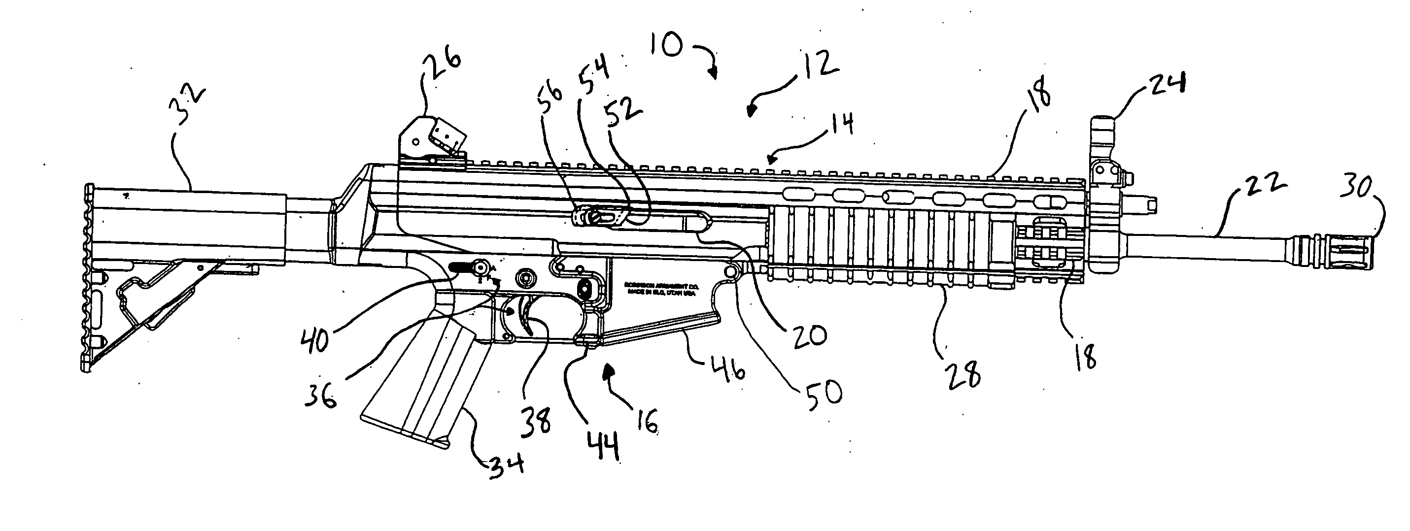
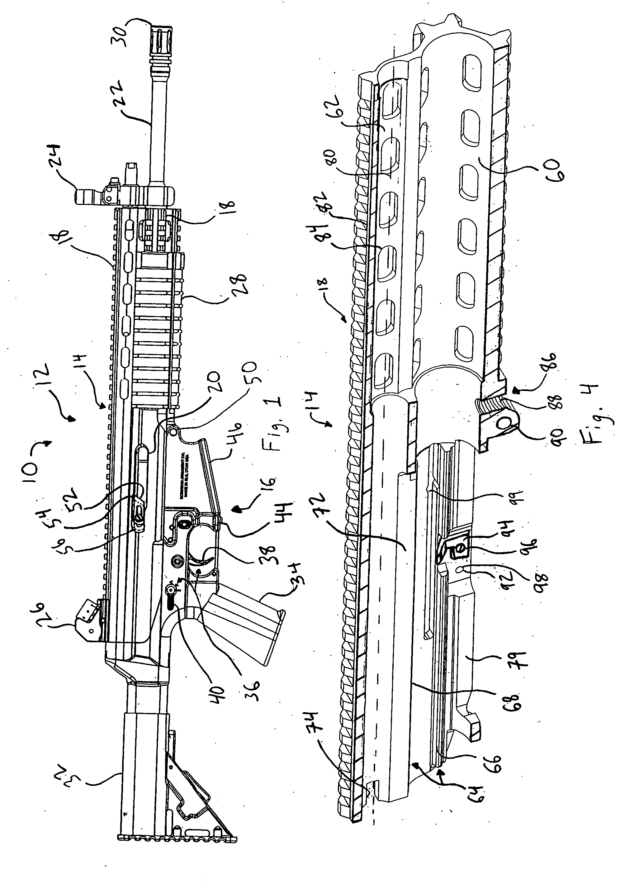
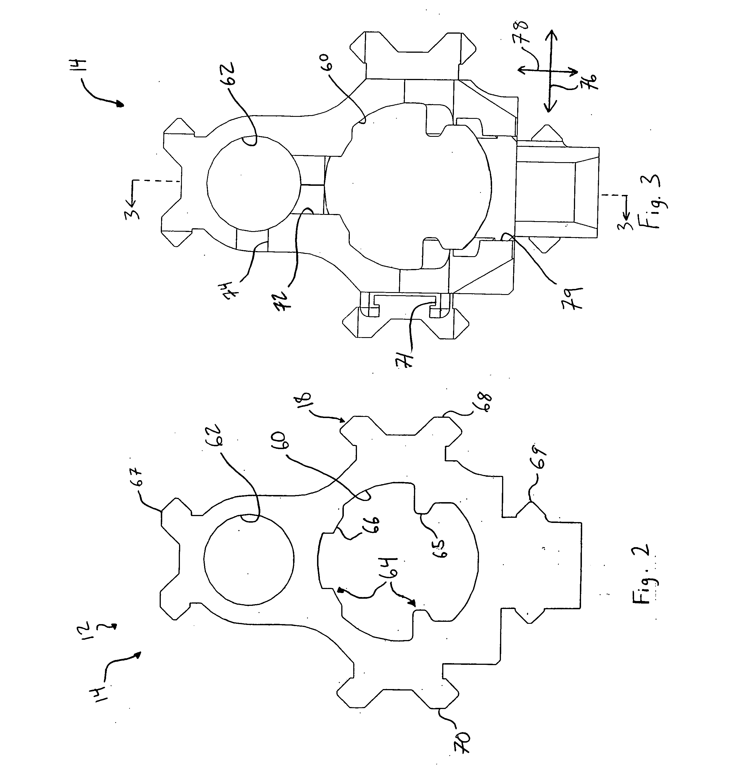
[0053] The presently preferred embodiments of the present invention will be best understood by reference to the drawings, wherein like parts are designated by like numerals throughout. It will be readily understood that the components of the present invention, as generally described and illustrated in the figures herein, could be arranged and designed in a wide variety of different configurations. Thus, the following more detailed description of the embodiments of the improved firearm of the present invention, as represented in FIGS. 1 through 14, is not intended to limit the scope of the invention, as claimed, but is merely representative of presently preferred embodiments of the invention.

[0054] For this application, the phrases “connected to,”“coupled to,” and “in communication with” refer to any form of interaction between two or more entities, including mechanical, electrical, magnetic, electromagnetic, and thermal interaction. The phrase “attached to” refers to a form of mech...


PUM


Abstract

A firearm including a barrel having a chamber and an integrally formed upper receiver having a passageway, an accessory rail extending the complete length of the upper receiver, and a guidance feature extending along the passageway. The firearm also includes an operating rod having an anti-bounce mechanism, a bolt that is rotated counter-clockwise to lock against the chamber, a bolt carrier having a safety extension disposed below the bolt that prevents a hammer from striking a firing pin until the bolt is locked against the chamber, a lower receiver, a recoil spring assembly, and a fire control group. The bolt includes a polymer spring that biases a sliding extractor against the base of a cartridge. The sliding extractor is disposed at an angle ranging from thirty degrees to fifteen degrees on the bolt face to provide a low ejection angle from the firearm.

Description

CROSS-REFERENCED RELATED APPLICATIONS [0001] This application claims the benefit of U.S. Provisional Application No. 60 / 534,586, filed Feb. 13, 2004, entitled IMPROVED FIREARM by Alexander J. Robinson, Darin G. Nebeker, and Jon C. Holway and is hereby incorporated herein by reference. This application is also a continuation-in-part of prior application Ser. No. 10 / 911,963, filed Aug. 4, 2004, entitled MULTI-CALIBER AMBIDEXTROUSLY CONTROLLABLE FIREARM by Alexander J. Robinson, Darin G. Nebeker, and Jon C. Holway and is hereby incorporated herein by reference.BACKGROUND OF THE INVENTION [0002] The present invention relates to firearms. More specifically, the present invention relates to firearms that can be quickly configured with a minimum of additional parts to fire different calibers of ammunition with improved reliability in harsh environmental and firing conditions. [0003] Currently available firearms have many limitations that can potentially place a user at risk, require long m...

Claims


Application Information

Patent Timeline
IPC IPC(8): F41A3/36F41A5/12F41A5/18F41A11/00F41A15/14F41A17/00F41A17/42F41A17/76F41A19/43
CPCF41A3/26F41A3/36F41A3/70F41A5/12F41A5/18F41A21/485F41A11/00F41A15/14F41A17/42F41A17/76F41A19/43F41A5/24F41A3/66
Inventor ROBINSON, ALEXANDER J.NEBEKER, DARIN G.HOLWAY, JON C.
Owner RMDI
Why Eureka
Try Eureka