Window and door sub-sill and frame adapter and method of attaching a sill

a technology for sliding glass doors and windows, applied in door/window fittings, building components, constructions, etc., can solve the problems of high installation cost, high installation cost, and high installation cost, and achieve the effect of superior strength and water prevention capability

Inactive Publication Date: 2005-12-01
CONSTR CONCEPTS UNLTD
View PDF3 Cites 36 Cited by
  • Summary
  • Abstract
  • Description
  • Claims
  • Application Information

AI Technical Summary

Benefits of technology

[0011] It is accordingly an object of the invention to provide an apparatus and method for securing a door or window sill to a supporting structure of a building, while utilizing fewer screws than the prior-art method and resulting in a sill that is superior in strength and water prevention capability.

Problems solved by technology

Clearly, this is a very labor intensive and expensive process of installation.
Driving screws into the slab presents the possibility of hitting any one of these infrastructural items.
Accordingly, the more screws that have to be driven, the higher the probability of hitting the infrastructure.
This problem is aggravated by the placement of flooring material, such as ceramic tile, outside the sliding-glass door and near the sill.
The placement of flooring material against the sill substantially blocks the weeping holes and prevents proper drainage from the sill.
Another problem with prior art sills is that the underside of the sill does not present a flat surface.
This presents a problem when the building structure that they are to be installed upon is not flat and / or smooth.
The grout messy, requires two components, is hard to work with, and drying time must be added to the installation process.
If the bottom of the sill does not present a flat surface to rest upon the shim, shimming is difficult and sometimes ineffective.
As the rollers of the door travel along the sill, they will encounter areas of resistance as they attempt to climb the peaks of the sill at the supported areas.

Method used


Image

  • Window and door sub-sill and frame adapter and method of attaching a sill
  • Window and door sub-sill and frame adapter and method of attaching a sill
  • Window and door sub-sill and frame adapter and method of attaching a sill

Examples


Embodiment Construction

[0030] While the specification concludes with claims defining the features of the invention that are regarded as novel, it is believed that the invention will be better understood from a consideration of the following description in conjunction with the drawing figures, in which like reference numerals are carried forward.

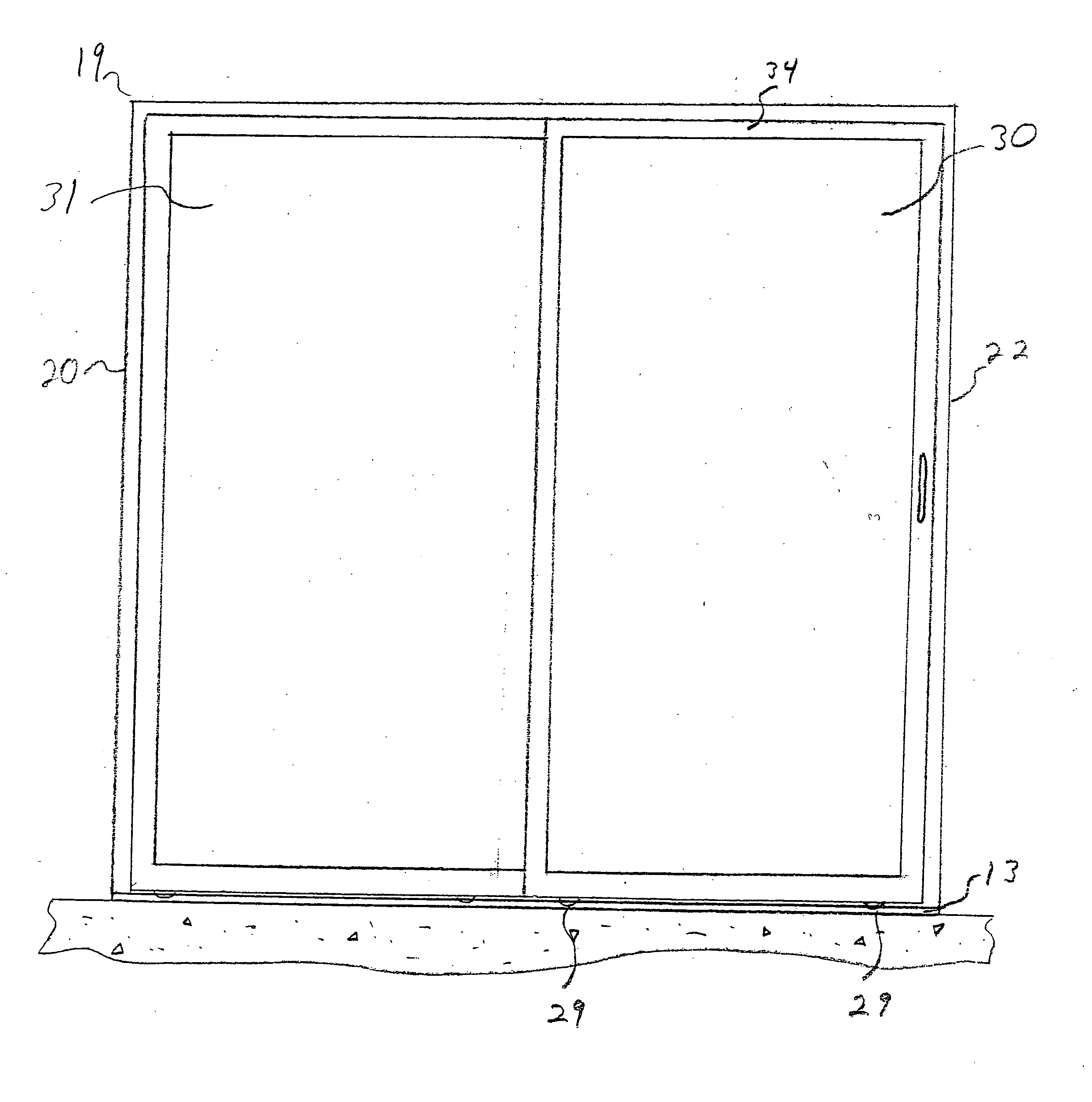
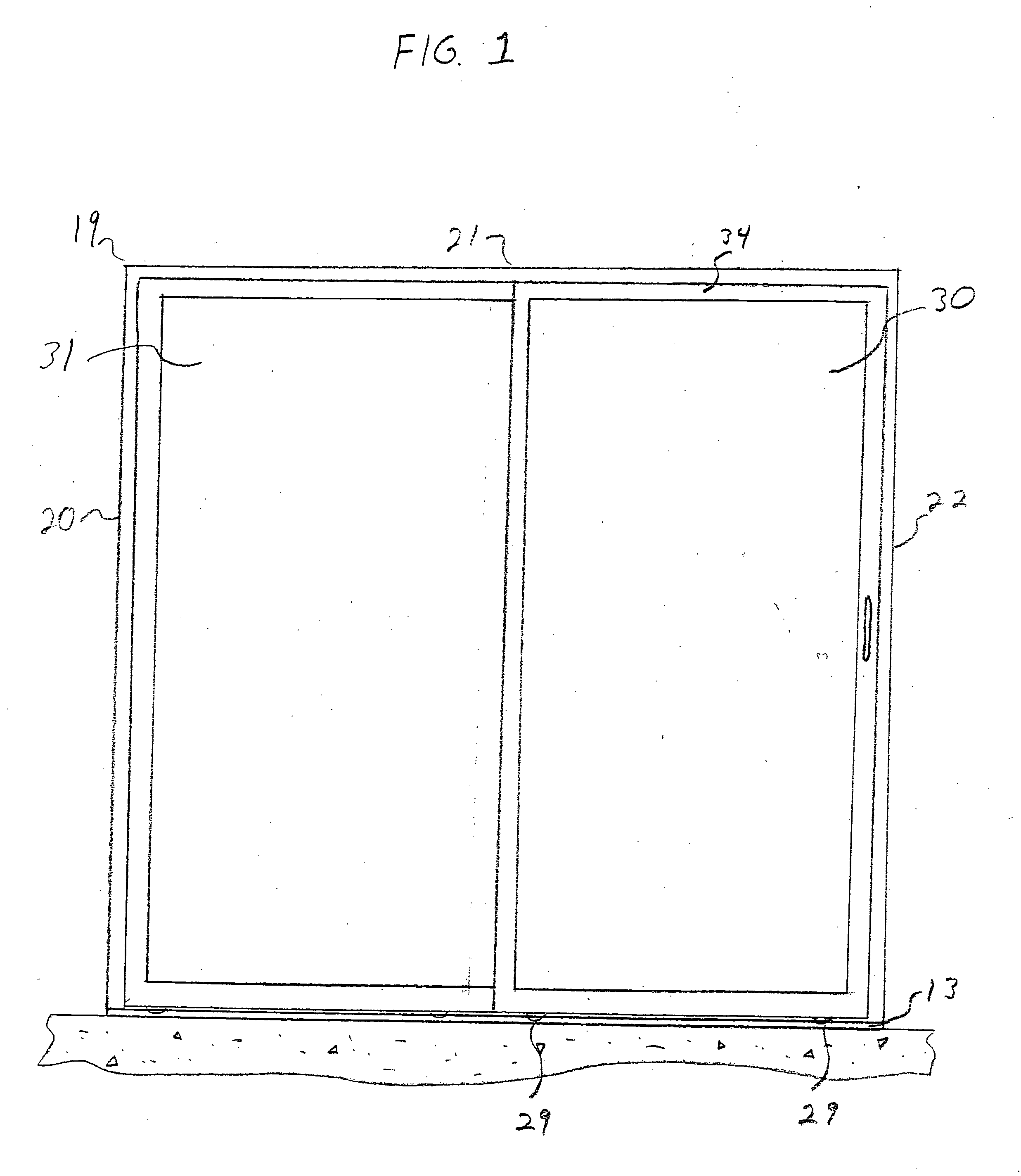
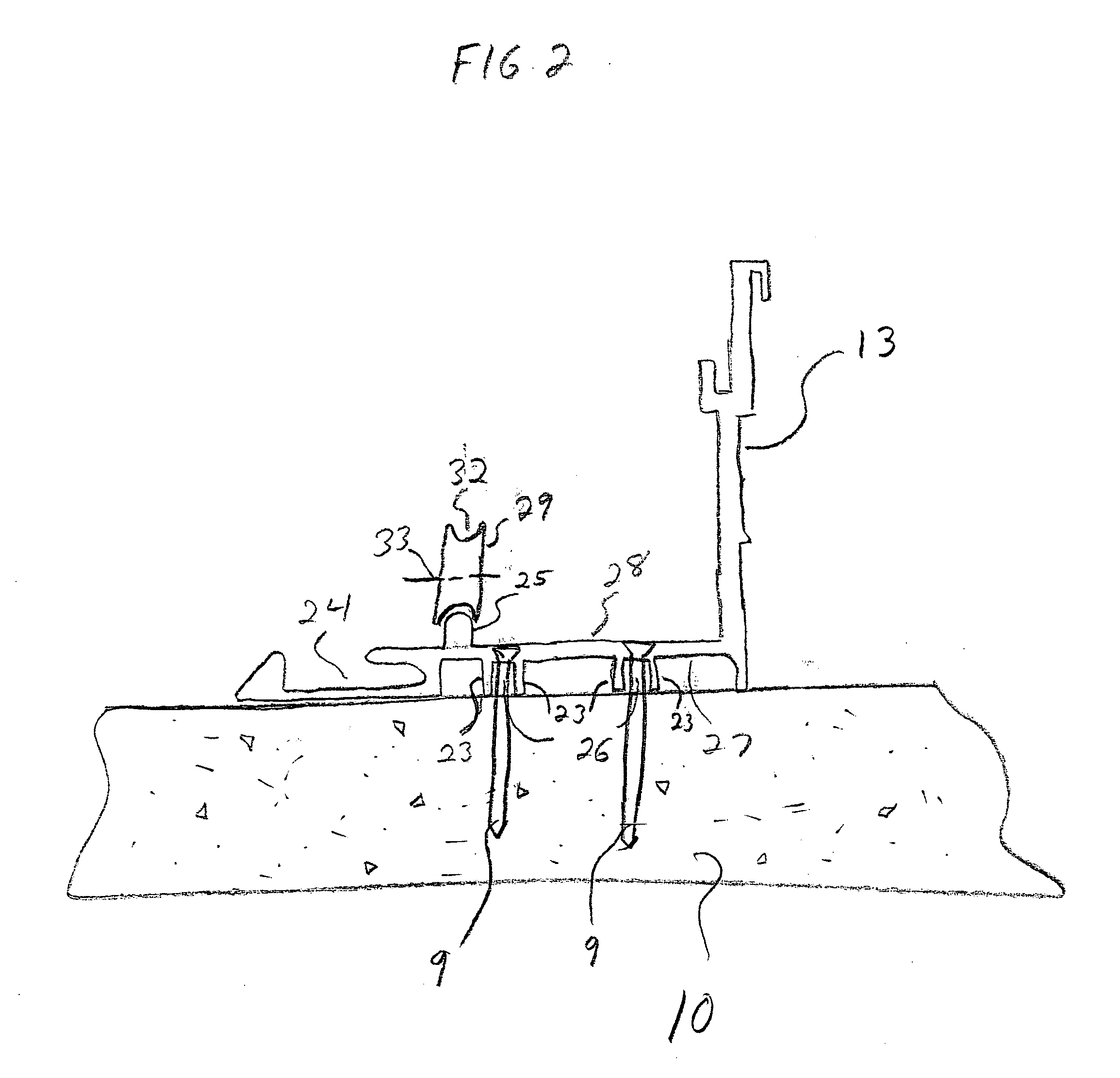
[0031] Referring now to the figures of the drawings in detail, and in particular to FIG. 1, there is illustrated a door frame 19 having elements 20, 21, 22, and sill 13. Elements 20, 21, and 22 are elongated hollow bodies having opposing wall elements which are disposed inwardly toward door panels 30 and 31 and form a U-shaped channel in which door panels 30 and 31 are seated. A cross-sectional view of the fourth frame element, sill 13, can be seen in FIG. 2. Sill 13 is generally constructed from aluminum. The underside 27 of sill 13 has downwardly extending opposing sets of walls 23, which define cavities 26. Cavities 26 present channels in which masonry screws 9...


PUM


Abstract

An apparatus and method for attaching a window or door sill to a building support structure is provided. The apparatus includes a rectangular frame that is attachable to a building support structure and provides an upper surface for a sill, to be securely attached to the apparatus. The apparatus thereby provides a raised surface with which to attach the sill. The apparatus includes a lip, which helps align the sill along the upper surface of the apparatus, and also helps prevent water intrusion. The apparatus further includes a support vein that runs through the center and along the length of the apparatus to provide added support strength.

Description

BACKGROUND OF THE INVENTION [0001] 1. Field of the Invention [0002] The invention relates primarily to sliding-glass doors and windows in residential and commercial buildings. More specifically, the present invention is directed to securing a sliding-glass door or window to a building structure. [0003] 2. Description of the Related Art [0004] Sliding-glass doors and windows are well known in the prior art. Both are popular in many homes, apartment buildings, condos, office buildings, and other similar structures. Sliding-glass doors and windows provide an aesthetically pleasing method of sealing the inside area of a structure from the outside environment while simultaneously allowing sunlight and warmth into a room. Sliding-glass doors have the added feature of also providing an easy method of entering or exiting a room. [0005] A sliding-glass door is one in which one or more panels are moveable, one or more are normally fixed, and the bottom of each panel is provided with rollers. ...

Claims


Application Information

Patent Timeline
Patent Type & Authority Applications(United States)
IPC IPC(8): E05D15/06E06B7/14
CPCE05D15/0686E06B7/14E05Y2900/148
Inventor GORMAN, CHRISTOPHER A.
Owner CONSTR CONCEPTS UNLTD
Why Eureka
Try Eureka