Fuel supply system

a technology of fuel supply and supply system, which is applied in the direction of turbine/propulsion fuel delivery, turbine/propulsion fuel valve, turbine/propulsion fuel control, etc., can solve the problems of “heat rejection”, difficulty of conventional system, and pump output exceeding demand

Inactive Publication Date: 2005-12-01
GOODRICH CONTROL SYST LTD
View PDF7 Cites 33 Cited by
  • Summary
  • Abstract
  • Description
  • Claims
  • Application Information

AI Technical Summary

Benefits of technology

[0012] In accordance with the present invention there is provided a fuel supply system for a gas turbine engine including first and second positive displacement pumps operated simultaneously to supply fuel under pressure from a low pressure source, a combining spill valve controlling the output flows from the first and second pumps to combine the outputs of the first and second pumps for supply to a metering valve of the system, or to spill some or all of the output of one or both pumps back to the low pressure supply, pressure raising and shut off valve means downstream of the metering valve for isolating the fuel system from an associated engine until the fuel pressure upstream of the pressure raising and shut off valve means exceeds a predetermined pressure, and, means dependent upon the position of the combining spill valve for reducing said predetermined pressure at which said pressure raising and shut off valve means opens.

Problems solved by technology

Thus there will be many operating conditions, notably engine idle conditions where the output of the pump exceeds the demand of the engine.
A recognised difficulty of the conventional system described briefly above is known as “heat rejection”.
When the gear pump is pumping fuel against system pressure then the action of spilling fuel in excess of engine demand to the low pressure side of the system results in heating of the fuel.
In addition, energy from the engine is wasted in heating the fuel through heat rejection at the fuel pumps thus resulting in an overall increase in engine fuel consumption.
Operation of the PRSOV to maintain pressure upstream of the PRSOV can cause difficulties during windmill relight in that the rotational speed of the engine shaft, and thus the rotational speed and output of the gear pump is insufficient to provide the pressure rise in the fuel metering system necessary to open the PRSOV for fuel to be supplied to the engine to allow the engine to start (relight).
Internal leakage within the pump, and parasitic flows in the fuel system can exacerbate the problem, but even when such internal leakage and parasitic flows are minimised the pump still may not be capable of delivering sufficient pressure rise into the system to open the PRSOV at windmill relight speeds.
However, use of such a passive restrictor would negate the heat rejection advantages of using twin gear pumps rather than a single gear pump as the gear pump whose output is not needed and which is being spilled back to the low pressure side, would then be pumping fuel against a pressure rise caused by the passive restrictor, and heating of the spilled fuel would result.

Method used


Image

  • Fuel supply system
  • Fuel supply system
  • Fuel supply system

Examples


Embodiment Construction

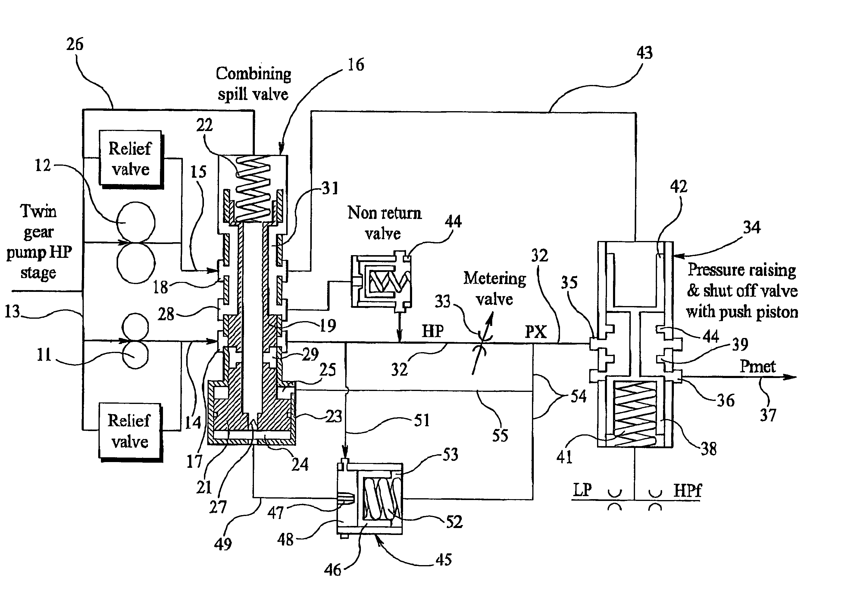
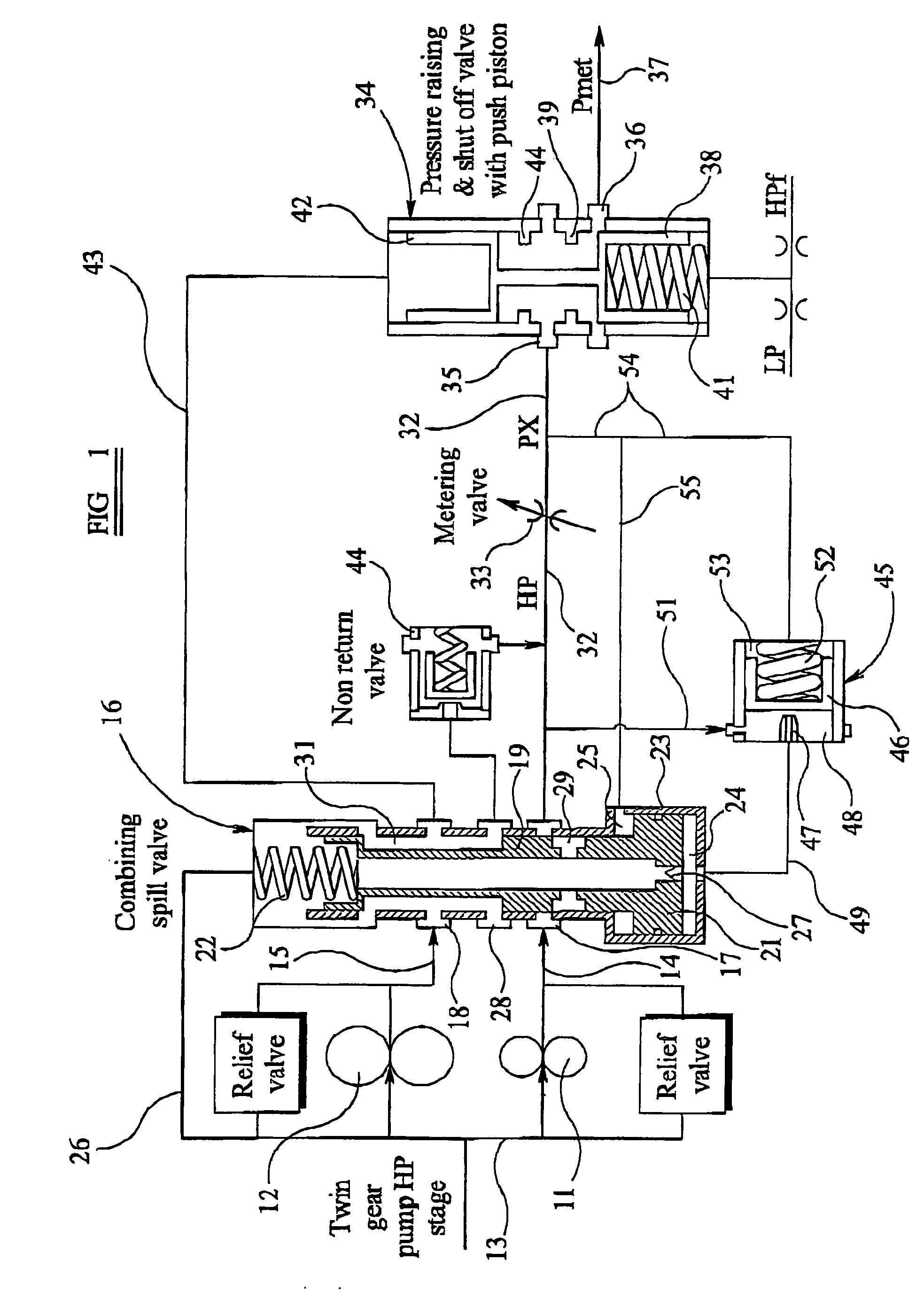
[0021] Referring first to FIG. 1 of the drawings the fuel supply system includes first and second gear pumps 11, 12 both of which are driven simultaneously from the gas turbine engine through a conventional accessory gearbox. The inlet ports of the pumps 11, 12 are connected to a low pressure line 13 of the fuel supply system, the line 13 being supplied with fuel at low pressure few a reservoir by a low pressure pump. The output ports of the pumps 11, 12 are connected through respective output lines 14, 15 to respective inlet galleries 17, 18 in the housing of a Combining Spill Valve (CSV) 16. Conventional pressure relief valves are connected across the pumps 11, 12 between their output lines and the low pressure line 13 to provide a discharge route for fuel back to the line 13 in the event of a blockage or an excessive build-up of fuel pressure downstream of the pumps. Normally however the relief valves do not open.

[0022] Movable axially within the housing of the CSV 16 is a spool...


PUM


Abstract

A fuel supply system for a gas turbine engine including first and second positive displacement pumps operated simultaneously to supply fuel under pressure from a low pressure source, a combining spill valve controlling the output flows from the first and second pumps to combine the outputs of the first and second pumps for supply to a metering valve of the system, or to spill some or all of the output of one or both pumps back to the low pressure supply, a pressure raising and shut off valve arrangement downstream of the metering valve for isolating the fuel system from an associated engine until the fuel pressure upstream of the pressure raising and shut off valve arrangement exceeds a predetermined pressure, and, a control system dependent upon the position of the combining spill valve for reducing said predetermined pressure at which said pressure raising and shut off valve arrangement opens.

Description

TECHNICAL FIELD [0001] This invention relates to a fuel supply system for a gas turbine engine, primarily, but not exclusively, an aircraft gas turbine engine. BACKGROUND ART [0002] A conventional fuel supply system uses a positive displacement pump, for example a gear pump, driven from the gas turbine engine trough the intermediary of an accessory gearbox, to provide fuel through a fuel metering system to the burners of the gas turbine engine. The positive displacement pump which, in the interests of clarity will be referred to herein as a “gear pump”, receives fuel from a fuel supply through a low pressure lift pump or the like, and it will be recognised that the rotational speed of the gear pump, and thus the output of the pump is directly proportional to the shaft speed of the gas turbine engine. Generally the capacity and therefore the size of the pump is calculated on the basis of the maximum fuel flow which will be needed in use, and of course a safety margin is applied on to...

Claims


Application Information

Patent Timeline
Patent Type & Authority Applications(United States)
IPC IPC(8): F02C7/232F02C7/236F02C9/26F02C9/32F02C9/36
CPCF02C7/232F02C7/236F02C9/36F02C9/32F02C9/263
Inventor YATES, MARTIN KENNETHELLIOTT, PHILIP LAURENCE
Owner GOODRICH CONTROL SYST LTD
Why Eureka
Try Eureka