
Computer-aided three-dimensional bending of spinal rod implants, other surgical implants and other articles, systems for three-dimensional shaping, and apparatuses therefor

a technology of spinal rod implants and three-dimensional shaping, applied in the field of computer-aided design and construction of medical implants and to surgical procedures, can solve the problems of poor resolution of current clinical paradigm for designing and shaping surgical corrective instruments, high personnel intensity, and process that is both tiring and involving increased risks for patients, and achieves global accuracy.

Inactive Publication Date: 2005-12-01
VIRGINIA POLYTECHNIC INSTITUTE AND STATE UNIVERSITY +1
View PDF14 Cites 165 Cited by
  • Summary
  • Abstract
  • Description
  • Claims
  • Application Information

AI Technical Summary

Benefits of technology

[0070] Before automated rod-bending of the invention, spring-back could not accurately be corrected-for when imposing a manual bend, because even if a formula was known for how much to bend so that the right spring-back was provided to ultimately end at a desired angle, a human operator could only be so accurate in applying the degree of bending force wanted to over-bend so that upon release, spring-back to the desired bend would occur. However, a strong advantage of the present invention is that by using a machine to bend a rod, the machine can bend the rod incrementally, according to a mathematical formulation. A human operator could not achieve the finesse of incremental bending that a machine can achieve.
[0071] Examples of control software useable in the invention are, e.g., one or more of: control software depicting a desired three-dimensional shape, such as, e.g., control software using a virtual representation of a patient's spinal rod to compute local curvature and torsion and to generate a sequence of actuator commands that will ensure satisfactory reproduction of the desired shape in the rod-bending hardware; control software that translates a desired target shape (received from the translational control interface) into a corresponding machine operation(s) such as, e.g., operation of an actuator or a motor; control software that processes actual measurement data from an angular-bend sensor and compares the actual measurement data to the desired target shape and, if needed, adjusts the sequence of actuator commands to ensure satisfactory reproduction of the desired shape (such as, e.g., control software that performs a local feedback operation; control software that performs a global feedback operation, etc.); etc.
[0072] In the case of rod-bending, an example of preferred control software used in the invention is control software which receives an actual angular bend measurement for a local bend just imposed, compares that actual angular bend measurement to the instruction that underlies that actual bend, and if the underlying instruction and actual angular bend measurement are at variance, reformulates the set of remaining bending instructions. For example, if the machine-based bending instruction was that the force-application mechanism was instructed to impose a 40 degree local bend, but the post-bend actual measurement received from the sensor for the local bend shows a 39 degree local bend actually was imposed, then the control software recognizes the discrepancy and recalculates the remaining force-application instructions to retain global accuracy and to achieve the desired shape. By doing so, advantageously in the present invention re-bending or placing bends on top of each other can be avoided.
[0073] The control software used in the invention preferably includes, for each material composition to be placed in the apparatus for shaping, at least one computer-readable table correlating each example of a desired angular bend to respective corresponding machine instructions for operating the force-applying mechanism to deliver the desired angular bend. That is, a titanium rod and a steel rod of the same diameter require different computer-readable tables of machine operation instructions because those different materials have non-identical elasticity or spring-back.
[0074] Optionally, there may be included in inventive systems and methods an automated pre-screening of the product being constructed. For example, in the case of a bent-rod medical implant which is to be connected to cooperating screws, there may be during construction of the bent-rod a step of confirming that imposition of a particular local bend in the rod will allow for cooperative placement of the screws. Another pre-screening example is of a pre-screening assessment of where a patient's spine may receive attachment of the rod being constructed.
[0075] Making an automated rod-bender apparatus may be readily accomplished with reference to the above-mentioned regular operation of an automated shaping apparatus such as an automated rod-bender, and with reference to the figures, photographs and Examples included herein, and the following remarks.

Problems solved by technology

The current clinical paradigm for designing and shaping the surgical corrective instrumentation is poorly resolved and highly personnel intensive.
This part of a surgery may take up to several hours, and this process is both tiring to the surgeon and involves increased risks to the patient.
However, these manual rod benders have limitations for what shapes can be created, the amount of force and time required to bend a rod, and inability to precisely create a desired shape because of a material upon being released from the manual bending device not holding the bend.
Such manual bending of spinal rods is a strenuous exercise.
In addition to requiring significant physical effort, a successful transition from many small bends to a desired overall curvature requires significant experience.
As local errors have long-range effects on the overall shape of the rod, after-the-fact corrections are often superposed on prior bends in a trial-and-error fashion thus reducing the accuracy of the bends and stressing the material.
This only reduces the effort required by the surgeon in achieving the desired shape and results in a smoother final rod contour as compared to manual rod benders, and much work and time on the part of a surgeon still is needed.
For example, this system offers no assistance to a surgeon in formulating a desired shape of the rod.
There is no automated imposition of curvature and torsion, and consequently this system is restricted to planar rods.
's system is not designed to handle the large bends required for thoracolumbar rod implants.
While some automated three-dimensional rod benders may be found in non-clinical settings, none are suitable for forming thoracolumbar rod implants.
Although this machine is capable of creating some three-dimensional bends, it does not address the imposition of large three-dimensional bends and clearance for the already bent portion of the rod that is necessary for the thoracolumbar rods.
There may also be issues with the resolution of the machine, which refers to the typical distance between bends that the machine is designed to accommodate.
Another non-clinical rod bender is U.S. Pat. No. 6,434,995, “Method of bending small diameter metal pipe and its apparatus.” This automated bending device imposes local curvature and torsion through a sequence of feeding, rotating, and bending commands, but does not address the imposition of large terminal three-dimensional bends and the required clearance for the long thoracolumbar rods.
Thus, conventional spinal surgery retains time-consuming manual components which have not been able to be reduced or eliminated.

Method used


Image

  • Computer-aided three-dimensional bending of spinal rod implants, other surgical implants and other articles, systems for three-dimensional shaping, and apparatuses therefor
  • Computer-aided three-dimensional bending of spinal rod implants, other surgical implants and other articles, systems for three-dimensional shaping, and apparatuses therefor
  • Computer-aided three-dimensional bending of spinal rod implants, other surgical implants and other articles, systems for three-dimensional shaping, and apparatuses therefor

Examples


##ventive example 2

INVENTIVE EXAMPLE 2

[0103] A preferred example of a use of the present invention is a method in which, in advance of surgical implantation, automated pre-screening of a three-dimensional bent shape is performed, including a determination of placement in the patient of the three-dimensional bent shape with reference to cooperating hardware placed, or to be placed, in the patient.

[0104] An example of cooperating hardware placed, or to be placed, in the patient is a pedicle screw, which is medical hardware conventionally in use, such as pedicle screw used in spinal surgery. An example of a three-dimensional bent shape is a bent spinal rod. The pedicle screws are used in attaching the spinal rod to the patient's body. In the invention, placing the bent spinal rod in the patient may be assisted by an inventive article that cooperates with the pedicle screw, such as a cap for the pedicle screw. An example of an inventive pedicle screw cap is a pedicle screw cap, comprising an article havi...


PUM

PropertyMeasurementUnit
diameteraaaaaaaaaa
anglesaaaaaaaaaa
anglesaaaaaaaaaa

Abstract

An implantable rod can be bent three-dimensionally in an automated system, which is especially useful for pre-surgical formation of implantable spinal rods. When local and / or global feedback processing accompanies a series of shaping steps automatically imposed on a rod or other article being shaped into three-dimensional form, formation time may be expedited compared to manual creation, and shapes difficult or impractical to create manually may be constructed simply.

Description

[0001] Priority is claimed based on U.S. provisional application No. 60 / 541,953 filed Feb. 6, 2004, titled, “System for Computer-aided Three-dimensional Bending of Spinal Rod Implants.”DESCRIPTION [0002] 1. Field of the Invention [0003] The present invention is directed to computer-aided design and construction of medical implants and to surgical procedures, especially spinal surgery. [0004] 2. Background of the Invention [0005] Scoliosis affects about 2% of the population and is most commonly seen in children 10 years or older. The current clinical paradigm for designing and shaping the surgical corrective instrumentation is poorly resolved and highly personnel intensive. Corrective surgery typically involves the fixation of segments of the vertical column through the attachment of curved titanium rods to the spine through an arrangement of hooks and pedicle screws. [0006] The shaping of spinal rods is generally effected manually by a surgeon during surgery with the patient's spine...

Claims


Application Information

Patent Timeline
Patent Type & Authority Applications(United States)
IPC IPC(8): B21D7/14B21D11/10
CPCB21D11/10B21D7/14A61B17/8863
Inventor DANKOWICZ, HARRYLEO, DONALD J.BALLMER, ALLISONBEEMAN, JOHNDILLON, TRAVISLASSALETTA, ANTONIOO'CONNOR, RYAN
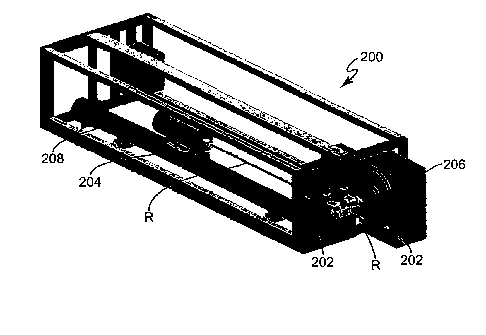
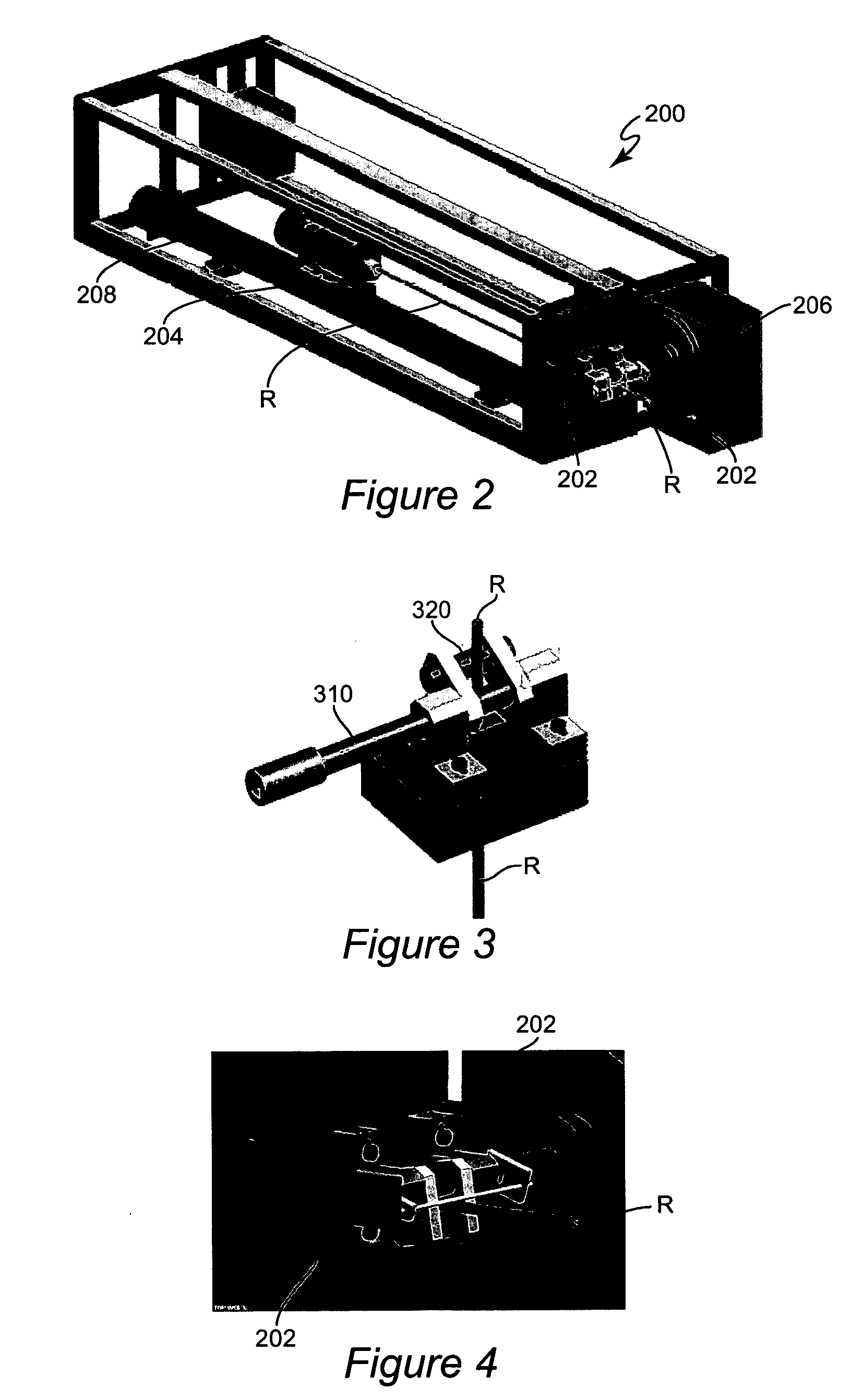
Owner VIRGINIA POLYTECHNIC INSTITUTE AND STATE UNIVERSITY
Learn More