Metal cutting apparatus and method for damping feed-back vibrations generated thereby

a technology of metal cutting tools and feed-back vibrations, which is applied in mechanical apparatus, auxiliaries, manufacturing tools, etc., can solve problems such as mechanical feedback vibrations, inability to accept machining, and technique work passably, and achieve the effect of improving the control of a vibration-damping devi

Inactive Publication Date: 2005-12-01
SANDVIK AB
View PDF11 Cites 15 Cited by
  • Summary
  • Abstract
  • Description
  • Claims
  • Application Information

AI Technical Summary

Benefits of technology

[0018] The purpose of the present invention is to improve the control of a vibration-damping device for cutting tools having a regenerative oscillatory motion.

Problems solved by technology

Each tool pass leaves disturbances in the form of undulations on the workpiece due to the vibrations of the tool and workpiece, and those disturbances produce mechanical feedback vibrations in subsequent passes of the tool.
Unstable conditions can cause a small wavelet to develop and increase around the circumference, giving non-acceptable machining results.
However, this technique works passably only in those cases where the overhang of the shaft from a fastening device is approx.
In addition to this limitation, the pure mechanical damping has an obvious disadvantage in that the range of frequencies within which the damping acts, is very limited.
An additional inconvenience consists of the strength-wise weakening of the shaft resulting from the presence of that cavity.
Thus, skis for alpine skiing (K2 Four ski, K2 Corp., USA) have been equipped with piezo elements for the purpose of suppressing undesired vibrations, which otherwise decrease the contact with the ground, and thereby reduce the skier's prospects of a stable and controlled skiing.
This type of vibration damper is not suitable for force-induced vibrations. but only for regenerative, i.e. feed-back vibrations, which, e.g., arise in a tool during mechanical machining when a small disturbance gives a mechanical feed-back in the tool.
Such a mechanical feed-back may cause an increasing oscillatory motion, and thereby an undesired uneven surface of the machined blank and reduced service life of the tool.
If a phase error arises, there is a risk of the oscillatory motion and the damping force ending up in an unbalanced state, and thereby partly amplifying each other, which in turn may lead to the oscillatory motion not being quenched to the desired degree.
This phenomenon constitutes a common problem, for instance during turning, especially internal turning, where the shaft in the form of a boring bar has to be long in order to reach the area in the workpiece which is to be machined, at the same time as the diameter of the bar is limited by the dimension of the bore in which machining is carried out.
During such drilling, turning and milling operations, where the distance to the workpiece is large, extenders are used, which frequently causes bending vibrations which not only lead to impaired dimensional accuracy and irregularities in the workpiece, but also to reduced service life of the tool and the cutting inserts or machining elements thereof.

Method used


Image

  • Metal cutting apparatus and method for damping feed-back vibrations generated thereby
  • Metal cutting apparatus and method for damping feed-back vibrations generated thereby
  • Metal cutting apparatus and method for damping feed-back vibrations generated thereby

Examples


Embodiment Construction

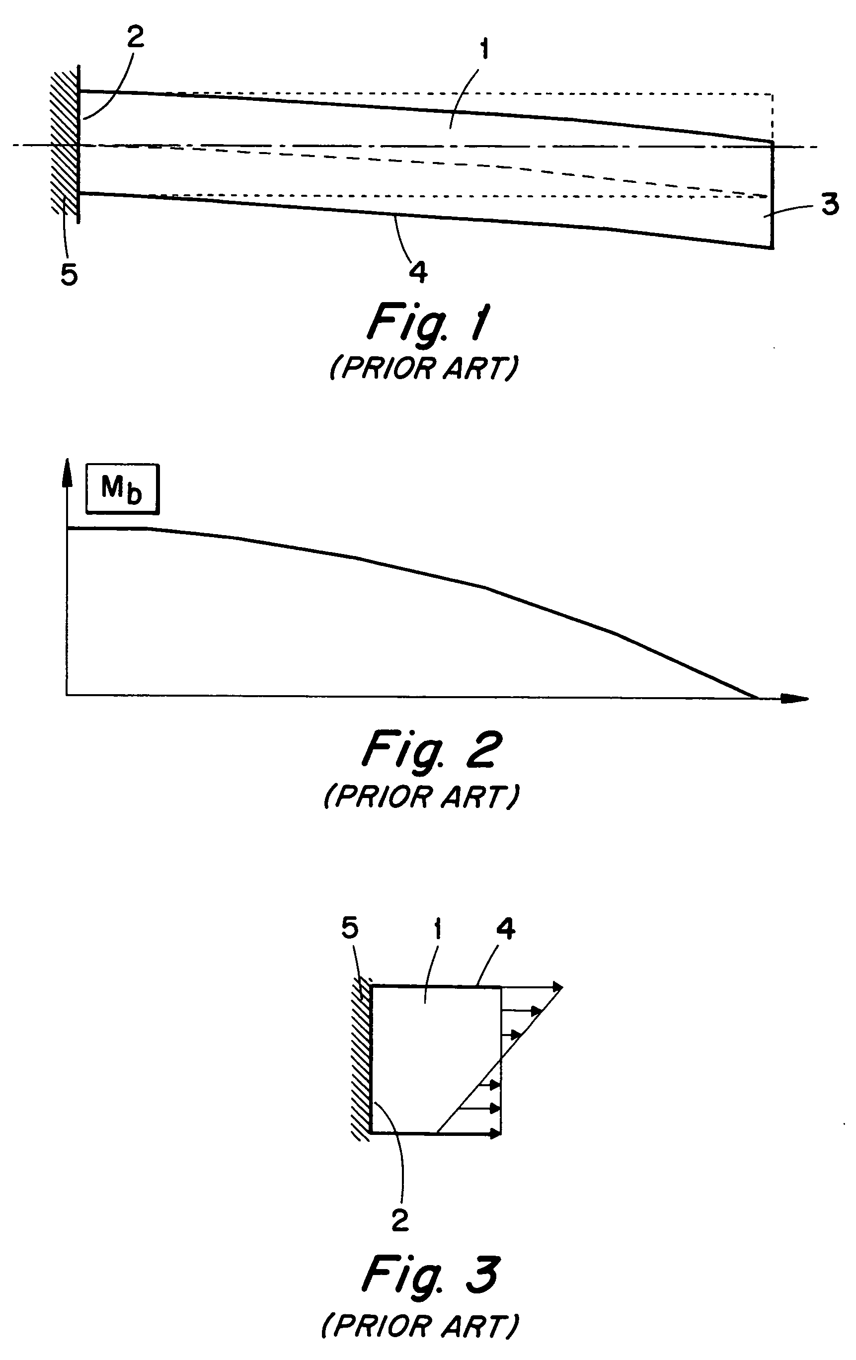
[0037] In FIG. 1, a long narrow body in the form of a bar or a shaft 1 of a tool is illustrated, which is intended to carry one or more (cutting) inserts of the tool during turning or milling. The body 1 has a fastening end 2 and a free, external end 3. The body has an external surface 4, which may be cylindrical or comprise a plurality of plane surfaces if the body has a polygonal, e.g. rectangular cross-section shape. The body 1 may have an arbitrary cross-section shape, however, most commonly circular or rectangular. In FIG. 1, numeral 5 designates a part in which the body 1 is fastened, the body extending cantilever-like from the fastening part. In FIG. 1, the body 1 is shown in a state when the same has been deformed in a first self-bending state or “own-mode.”

[0038] Furthermore, in FIG. 2 a graph is shown which illustrates how the bending torque Mb in this case varies along the body. As is seen in the graph, a maximum bending moment arises, and thus a maximum axial elongation,...


PUM

PropertyMeasurementUnit
frequenciesaaaaaaaaaa
frequencyaaaaaaaaaa
damping forceaaaaaaaaaa

Abstract

Feed back vibrations of a metallic tool generated during the machining of metallic workpieces are damped by detecting an oscillatory motion of the tool, identifying a frequency of the oscillatory motion and generating a mechanical camping force having the same frequency as the oscillatory motion and applied to the tool in counter-direction to a velocity of the oscillatory motion. The damping force can be of constant amplitude or gradually decreasing amplitude.

Description

[0001] This application claims priority under 35 U.S.C. §§ 119 and / or 365 to Patent Application Serial No. 0004540-1, filed in Sweden on Dec. 8, 2000, the entire content of which is hereby incorporated by reference. TECHNICAL FIELD OF THE INVENTION [0002] The present invention relates to the damping of feed-back vibrations generated by a metal cutting tool during the chip-removing machining of metal. In particular, the invention relates to a method of such damping which involves: [0003] detecting the tool's oscillatory motion by means of a sensor device associated with a control device, [0004] identifying the oscillatory motion's frequency, amplitude and phase by means of the control device, and [0005] by means of the control device, actuating a vibration damping device, so that the same renders a mechanical damping force with substantially the same frequency as the tool's oscillatory motion. [0006] The invention also relates to a vibration damper and a mechanical apparatus for perf...

Claims


Application Information

Patent Timeline
Patent Type & Authority Applications(United States)
IPC IPC(8): B23B3/00B23Q15/12B23B27/00B23B29/02B23C5/00B23Q11/00B23Q17/12F16F15/00
CPCB23B27/002Y10T82/2595B23B2250/16B23B2260/108B23B2260/1285B23C5/003B23C2250/16B23Q11/0039B23Q17/0971B23Q17/0976F16F15/005Y10S82/904Y10T409/10636Y10T408/76Y10T82/10Y10T409/304312B23B29/022B23Q11/00
Inventor LUNDBLAD, MIKAEL
Owner SANDVIK AB
Why Eureka
Try Eureka