Port rodder with velocity damper

a technology of velocity damper and port rodder, which is applied in the direction of pulp liquor regeneration, combustion types, lighting and heating apparatus, etc., can solve the problems of clogging, affecting the operation of precisely adjusted damper position for providing desirable furnace operating parameters, and affecting the effect of air flow

Active Publication Date: 2005-12-01
DIAMOND POWER INT
View PDF18 Cites 10 Cited by
  • Summary
  • Abstract
  • Description
  • Claims
  • Application Information

AI Technical Summary

Benefits of technology

[0005] A port rodder assembly in accordance with the present invention is positioned adjacent to an air port of a boiler and incorporates a reciprocating cutting head for periodically cleaning the air port to ensure that it is opened to permit air flow. A damper in the form of a pivoting wing is provided within the cassette assembly of the device which can be rotated between a fully opened configuration which maximizes air flow to a closed position which reduces the effective air flow area. The wing provides a streamline shape for interaction with the air flow to provide a penetrating, smooth air flow jet into the boiler through the air port. The assembly includes features which enable the cutting head to be reciprocated for cleaning without interference with the wing or requiring its position to be changed. In this way, cleaning operations produce a minimal change in air flow through the port rodder assembly.

Problems solved by technology

The nature of the fuel and the process conditions result in a tendency of plugging of the air ports, which are openings through which combustion air is supplied.
This clogging occurs through an accumulation of dust particles and flowing cinder products within the boiler.
Due to its turbulence, this air flow is not able to penetrate deeply into the boiler interior, and thus produces a stratification of the air flow and available oxygen within the boiler interior.
Thus, in such systems, the precisely adjusted damper position set for providing desirable furnace operating parameters is upset during the cleaning cycle.
This can produce undesirable transient operating conditions within the boiler.

Method used


Image

  • Port rodder with velocity damper
  • Port rodder with velocity damper
  • Port rodder with velocity damper

Examples


Embodiment Construction

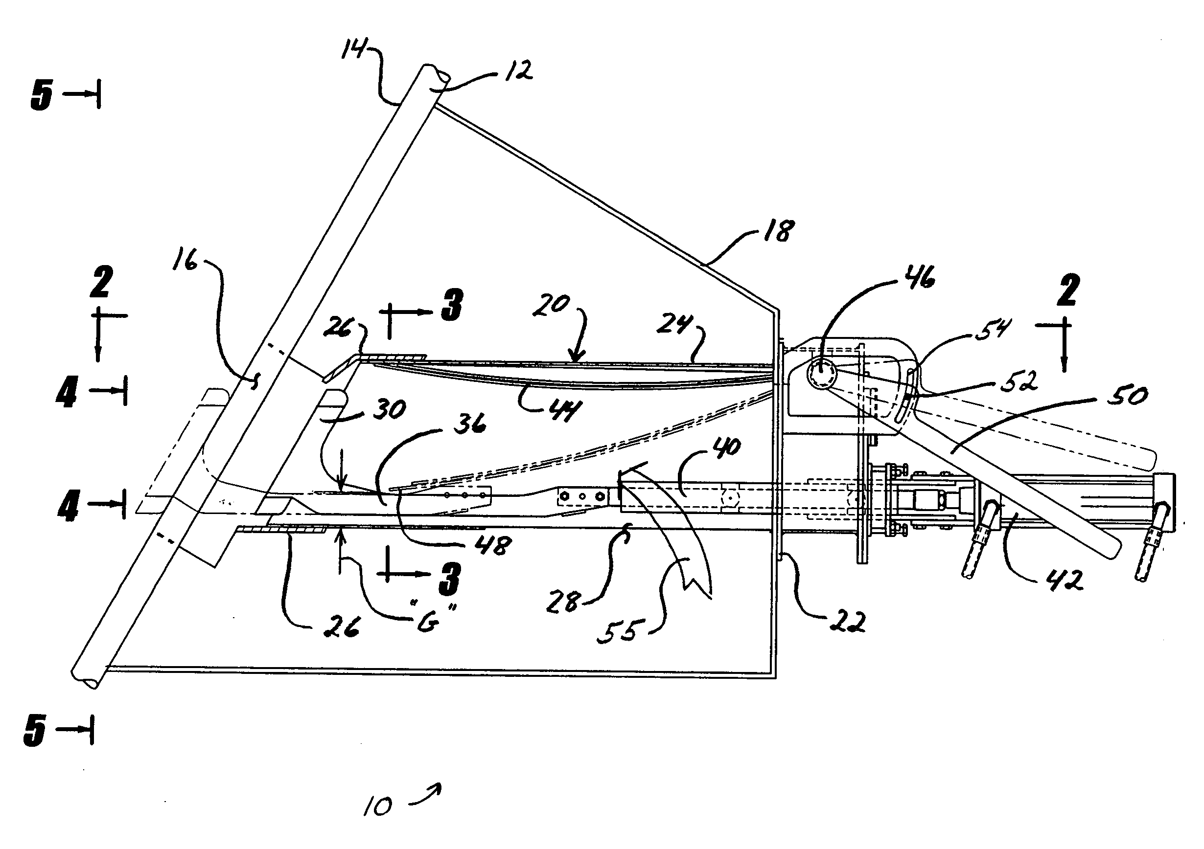
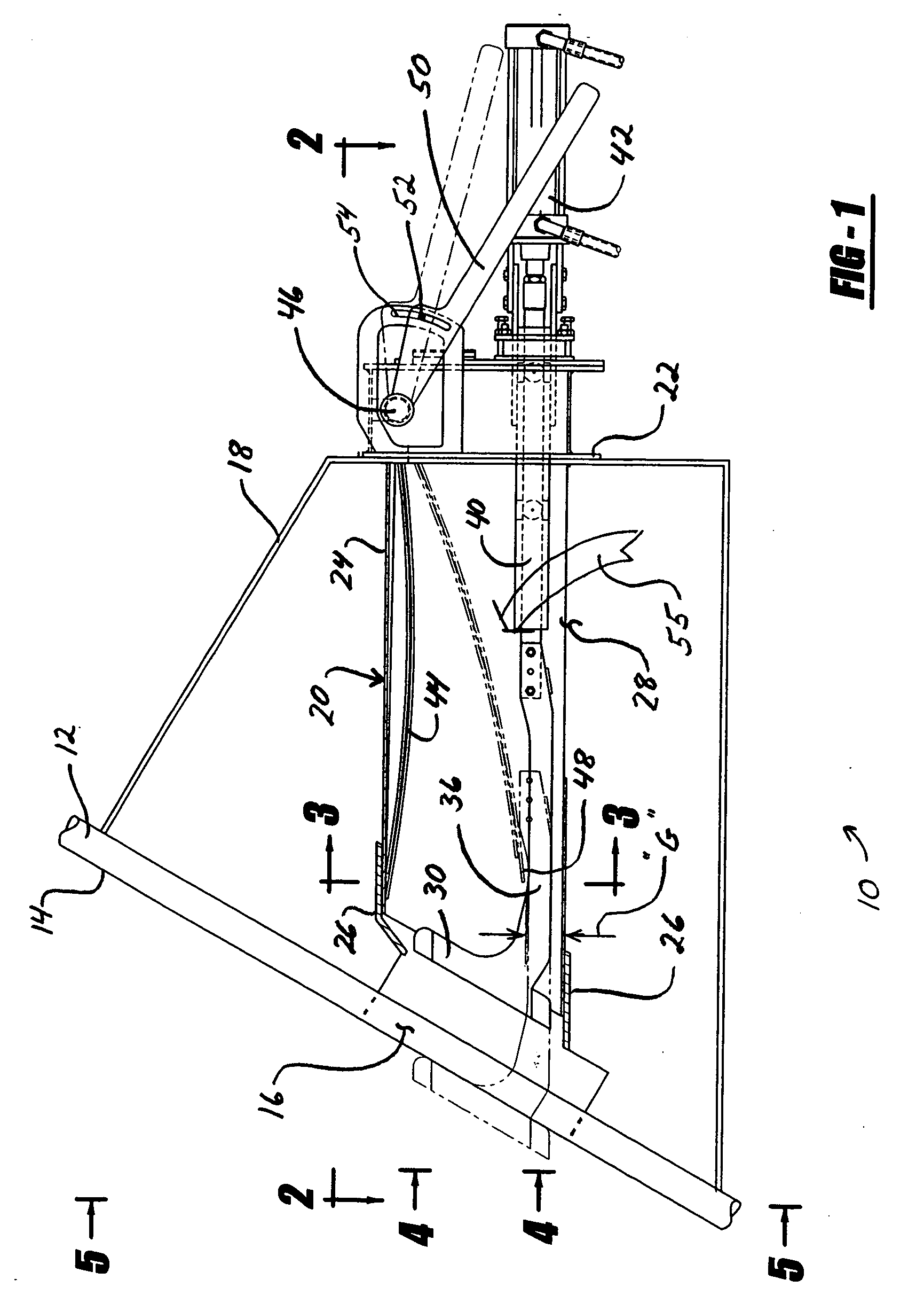
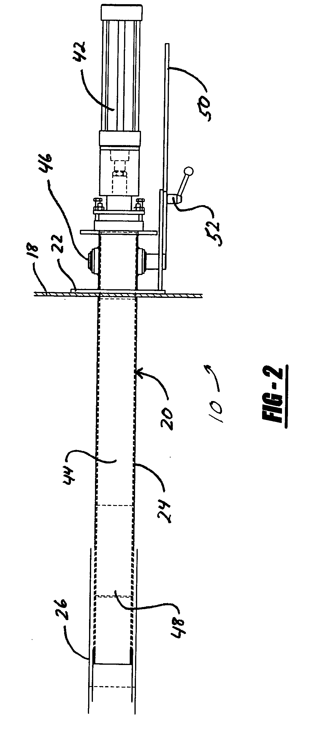
[0015] Referring to FIGS. 1-5, a port rodder assembly in accordance with the teachings herein is shown generally at 10. The port rodder assembly 10 is shown mounted to the exterior surface of a boiler outer wall 12. The outer wall incorporates boiler tubes 14 to conduct water or steam for removing heat from the combustion process occurring within the boiler. An air port 16 is formed within the boiler outer wall 12. The air port 16 defines a narrow rectangular slot which penetrates boiler wall 12 for the admission of combustion air, as previously described. A typical boiler will have a multiplicity of air ports 16, strategically arranged around the perimeter of the boiler to admit supplemental atmospheric air in desired quantities.

[0016] The port rodder assembly 10 is used with wind box 18 mounted to the exterior surface of the boiler outer wall 12. The wind box 18 is a sheet metal structure that is fastened to boiler wall 12 and provides support for the remaining components of the ...


PUM

PropertyMeasurementUnit
sizeaaaaaaaaaa
areaaaaaaaaaaa
air flow rateaaaaaaaaaa

Abstract

A port rodder assembly for a recovery boiler includes a duct affixed to and in fluid communication with an air port of the boiler, having a hollow interior, and an air inlet opening. A cutting head is slidably mounted within the duct adjacent to the air port and is adapted to clean the air port. An actuator selectively advances the cutting head though the air port to clean the air port. A wing is pivotally mounted within the duct. The wing interacts with the air inlet opening to control the flow of air through the duct and into the air port and is shaped such that incoming air flows smoothly through the duct to the air port.

Description

CROSS-REFERENCE TO RELATED PATENT APPLICATIONS [0001] This patent application claims the benefit of U.S. provisional patent application 60 / 575,633, filed May 28, 2004.FIELD OF THE INVENTION [0002] The present invention relates to a device for cleaning an air port arranged in the wall of a furnace and for regulating the flow of air through the air port which may be used, for example, in a recovery boiler or furnace. BACKGROUND OF THE INVENTION [0003] Within the cellulose production industry, the spent liquors from paper wood boiling (sulfate spent liquor and, in some cases, sulfite spent liquor) are combusted in a recovery boiler. The nature of the fuel and the process conditions result in a tendency of plugging of the air ports, which are openings through which combustion air is supplied. This clogging occurs through an accumulation of dust particles and flowing cinder products within the boiler. These pluggings are more accentuated in the lower regions of the air port and especiall...

Claims


Application Information

Patent Timeline
Patent Type & Authority Applications(United States)
IPC IPC(8): D21CF22B15/00F23J3/00F23L5/00
CPCF23J3/00D21C11/12F23L1/00F23L9/00F23L13/02D21C11/122F23G7/04F23L99/00
Inventor BERGMYREN, LEIF
Owner DIAMOND POWER INT
Why Eureka
Try Eureka