Embroidery frame for caps

a technology for embroidering frames and caps, which is applied in the field of embroidering frames for caps, can solve the problems of large space, increased cost of embroidery sewing machines, and unsuitability of cap frame devices of the above-described type for use with household embroidery sewing machines

Inactive Publication Date: 2005-12-01
BROTHER KOGYO KK
View PDF7 Cites 3 Cited by
  • Summary
  • Abstract
  • Description
  • Claims
  • Application Information

AI Technical Summary

Benefits of technology

[0013] The driving connectors are each formed so as to extend by a predetermined length in such a direction that the driving connectors depart from the sewing opening. Further, an attachment opening is defined between the driving connectors so that the attachment opening allows the visor of the cap held on the embroidery frame to escape from the sewing mechanism when the driving connectors are attached to the driver of the embroidery frame driving mechanism. Accordingly, when the embroidery frame holding the cap is attached to the sewing machine, the driving connectors extending to the proximal end side of the embroidery frame are disposed at both sides of the cylinder bed respectively. In this state, the embroidery frame can easily be caused to escape so that the visor is allowed to pass through gaps defined by a sewing needle and presser foot, while being swung vertically without being rotated right-and-left. Consequently, the driving connectors can easily be connected to the driver of the embroidery frame driving mechanism.

Problems solved by technology

As a result, the cost of the embroidery sewing machine is increased and a large space is necessary to accommodate the large drive motor.
Particularly, since household embroidery sewing machines are required to be purchased at a low cost and to be small in size, the cap frame device of the above-described type is unsuitable for the use with the household embroidery sewing machines.
In particular, stretching the embroidery part into a planar shape is a complicated work.
Thus, attaching the cap to the cap frame necessitates a lot of working time and labor, resulting in reduction in the working efficiency.

Method used


Image

  • Embroidery frame for caps
  • Embroidery frame for caps
  • Embroidery frame for caps

Examples


Embodiment Construction

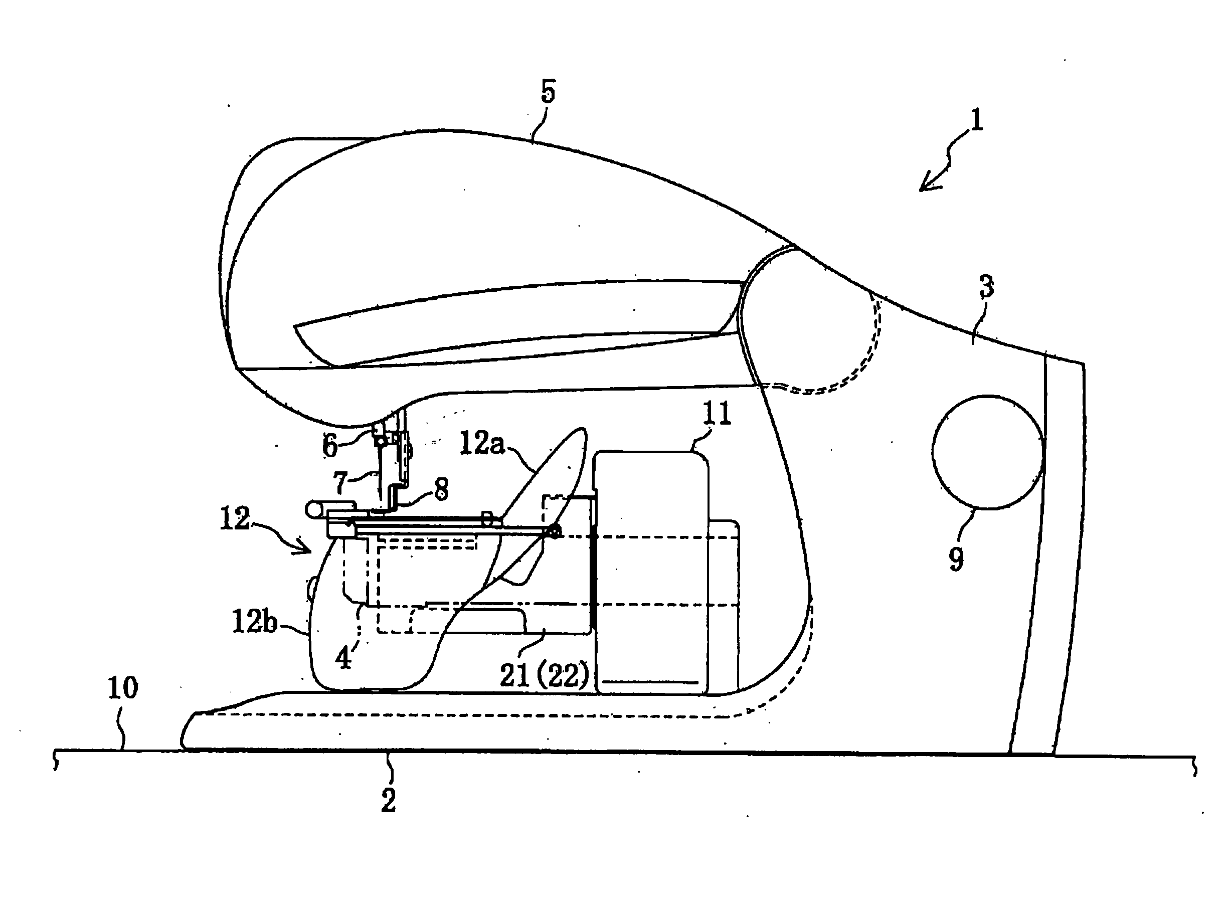
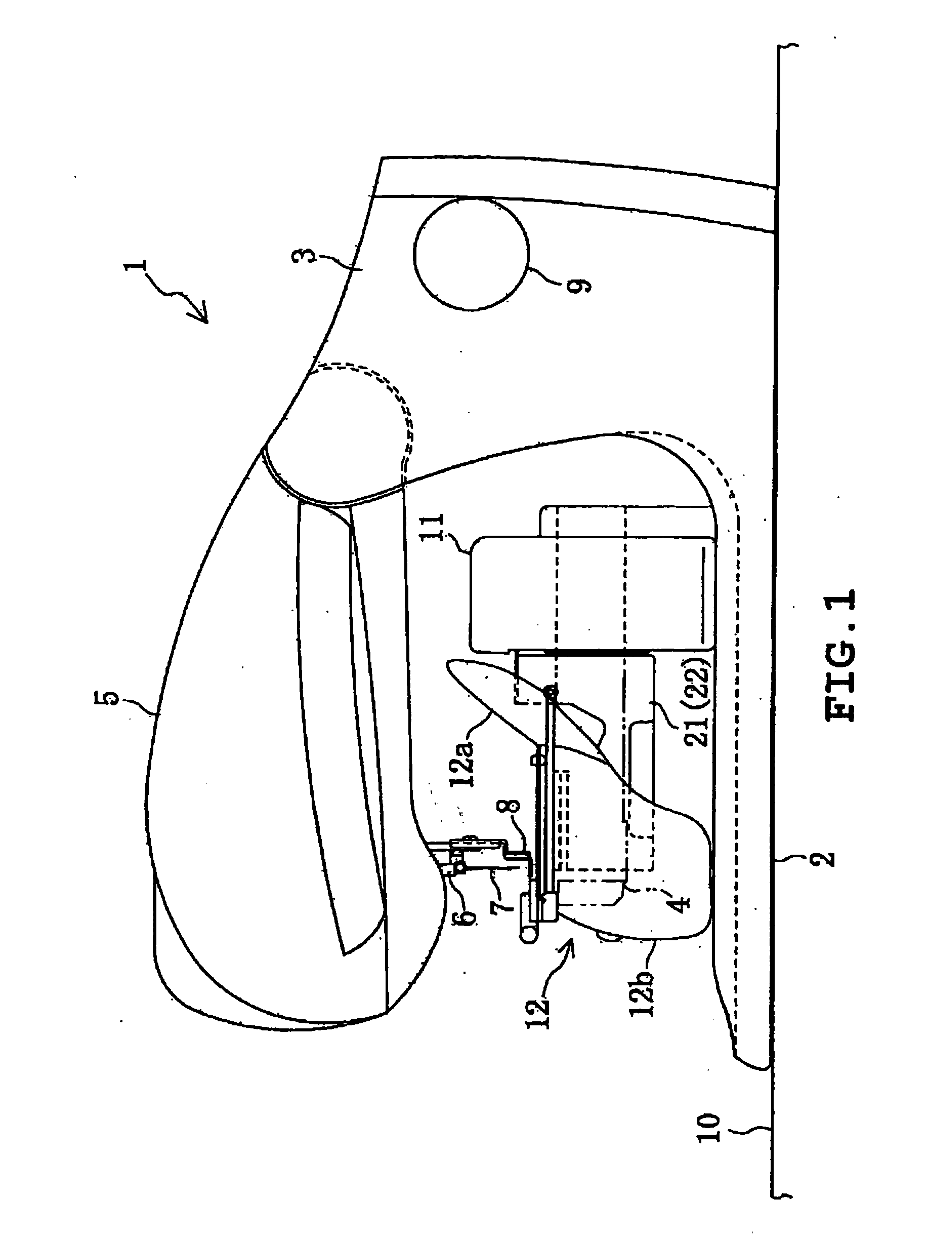
[0026] One embodiment of the present invention will be described with reference to the accompanying drawings. Referring to FIG. 1, an embroidery sewing machine 1 is shown as accompanied by an embroidery frame for caps in accordance with one embodiment. The embroidery sewing machine 1 includes a horizontal base 2 mounted on a work table 10 or the like, a pillar 3 standing from a rear end of the base 2, a cylinder bed 4 horizontally extending frontward from the pillar 3 and a sewing arm 5 extending frontward from an upper end of the pillar 3. The cylinder bed 4 extends back and forth. The front of the cylinder bed 4 constitutes a distal end whereas the rear thereof constitutes a proximal end.

[0027] The arm 5 is provided with a main shaft driven by a sewing machine motor, a needle bar driving mechanism vertically moving a sewing needle via a needle bar 6, a bobbin driving mechanism and a presser foot driving mechanism vertically moving a presser foot 8 none of which are shown. In the ...


PUM


Abstract

An embroidery frame for a cap includes a cap support having a pair of side walls capable of being disposed at both sides of a cylinder bed so that the side wall are parallel to a direction of extension of the cylinder bed, a pair of body supports mounted on the upper ends of the respective side walls for supporting a cap body of a cap on which embroidery is to be sewn, the body supports forming a sewing opening defining an embroidable region, the side walls including a pair of visor supports mounted on upper ends of the proximal ends of the side walls respectively, the visor supports receiving a visor of the cap from below at a position located higher by a predetermined height than the body supports and a pair of visor escapes provided on the side walls for escaping the visor of the cap respectively, the visor escapes being formed by cutting off the upper ends of the side walls respectively, and a cap pressing frame mounted so as to be brought into contact with and depart from the cap support, the cap pressing frame pressing, against the body support, the cap attached to the cap support so as to be fitted with the cap support.

Description

BACKGROUND OF THE INVENTION [0001] 1. Field of the Invention [0002] This invention relates to an embroidery frame for caps capable of sewing embroidery on a visored cap. [0003] 2. Description of the Related Art [0004] Various types of embroidery sewing machines have conventionally been proposed and practiced in which an embroidery frame for caps is attached thereto so that various types of embroidery patterns are sewn on an embroidery part of a cap supported by the embroidery frame. For example, JP-A-H11-200228 discloses a cap frame device provided with a rectangular cloth carriage frame moved in X and Y directions on a work table. X-direction and Y-direction driving mechanisms are provided for moving the cloth carriage frame in the X and Y directions respectively. Further, a sewing machine body frame includes a sewing bed body to which a rear end of a support shaft is secured. A base frame of the cap frame device is supported on the support shaft. The base frame is moved via a link...

Claims


Application Information

Patent Timeline
Patent Type & Authority Applications(United States)
IPC IPC(8): D05C9/04D05B39/00
CPCD10B2501/042D05C9/04
Inventor TERAO, AKIRA
Owner BROTHER KOGYO KK
Why Eureka
Try Eureka